Wiring Diagrams SiBE28-804
260 Appendix
4. Wiring Diagrams
4.1 Outdoor Unit
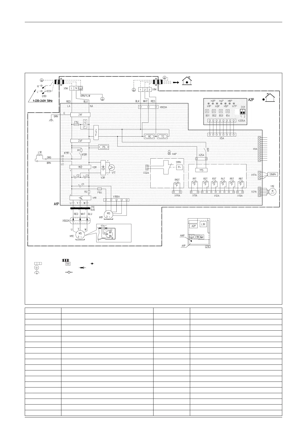
4.1.1 RZQ71C7, RZQS71·100C7V1B
The illustration below shows the wiring diagram of the unit.
Notes:
1. This wiring diagram only applies to the outdoor unit
2. L: Live, N: Neutral, : Field wiring
3. : Terminal strip : Connector :Connection
: Protective earth (screw) : Relay connector
: Noiseless earth : Terminal
4. Refer to the option manual, for connecting wiring to x6A.
5. Refer to the ''Wiring diagram sticker'' (on back of front plate) on how to use BS1∼BS4
and DS1 switch.
6. Do not operate the unit by short-circuiting protection device S1PH
7. Colours: WHT: White / RED: Red / BLU: Blue / ORG: Orange
BRN: Brown / GRN: Green / YLW: Yellow
8. Confirm the method of setting the selector switches (DS1) by service manual.
Factory setting of all switches: ''OFF''.
ON
OFF
Indoor
El. comp. Assy
Position of elements
(Front)
Position of
compressor
terminal
(Back)
Outdoor
(Note4)
A1P Printed circuit board (Main) R1T Thermistor (air)
A2P Printed circuit board (Inverter) R2T Thermistor (discharge)
BS1~BS4 Push button switch R3T Thermistor (Suction)
C1~C3 Capacitor R4T Thermistor (Heat exchanger)
DS1 Dip switch R5T Thermistor (Thermistor (heat exchanger middle))
F1U Fuse (T 6.3A / 250V) R6T Thermistor (liquid)
F6U Fuse (T 3.15A / 250V) R10T Thermistor (fin)
H1P~7P (A2P) Light emitting diode (service monitor orange) RC Signal receiver circuit
HAP (A1P) Light emitting diode (service monitor green) S1NPH Pressure sensor
K1R Magnetic relay (Y1S) S1PH Pressure switch (High)
K10R Magnetic relay TC Signal transmission circuit
K11R Magnetic relay V1R Power module
L1R Reactor V2R,V3R Diode module
M1C Motor (compressor) V1T IGBT
M1F Motor (fan) X1M Terminal strip (Power supply)
PS Switching power supply Y1E Electronic expansion valve
Q1DI Field earth leakage breaker (30mA) Y1S Solenoid valve (4 way valve)
R1 Resistor Z1C Noise filter (ferrite core)
R2 Resistor Z1F~Z4F Noise filter
 Loading...