IM 907 / Page 5 of 24
UDH-42
UDH-59
UDH-78
UDH-95
UDH-139
UDH-161
UDH-193
UDH-212
UDH-247
UDH-279
UDH-333
UDH-385
UDH-500
UDH-610
2
8
35
3
0
30
45
50
55
55
65
75
75
75
9
3
—
11
13
14
16
18
21
23
25
2
6
30
30
30
37
36
17
2
0
22
2
4
27
31
34
37
39
45
45
45
56
54
8
9
11
11
13
14
16
16
17
18
17
17
19
19
17
18
2
0
25
2
9
31
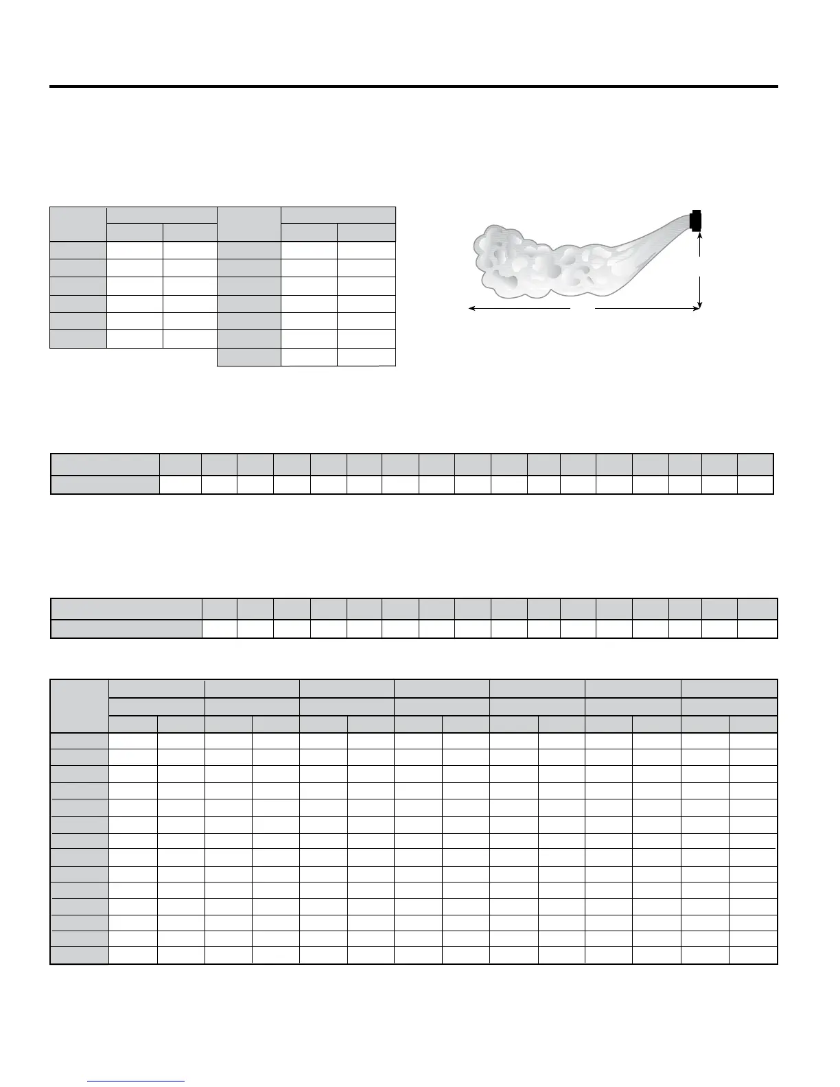
Height-Ft./Spread-Ft.
H
Unit Heater Mounting Height & Mounting Height Correction Factors
Do not install unit above recommended maximum mounting heights or below the minimum height of eight feet. The
height at which unit heaters are installed is critical. See Tables 1 thru 4. Maximum mounting heights for Model UDH is
given for units with or without air diffusion accessories.
H
S
Installation
Model
Size
S
UHH-18
UHH-24
UHH-33
UHH-47
UHH-63
UHH-86
9
9
10
12
14
15
Table 1. Horiz. Air Maximum Mounting Height and Spread
Note: Performance data for standard units at standard conditions of
200ºF entering water and 60ºF entering air.
Table 2. Mounting Height Correction Factors – Hot Water
Note: Factors are for use with entering air temperature ranging from 50°F to 70°F.
Water Temp. Drop, (°F)
Correction Factor
150
1.25
160
1.19
170
1.13
180
1.08
190
1.04
200
1.00
210
0.97
220
0.94
230
0.91
240
0.89
250
0.86
260
0.84
270
0.82
280
0.80
290
0.78
300
0.77
Table 3. Mounting Height Correction Factors – Steam
Steam Pressure (PSIG)
Correction Factor
2
1.00
5
0.97
10
0.94
15
0.92
20
0.89
30
0.86
40
0.84
50
0.8
2
60
0.80
70
0.79
80
0.77
90
0.76
100
0.75
125
0.74
150
0.7
2
175
0.71
H S
15
16
17
18
19
2
0
20
32
33
3
4
37
40
44
46
UHH-108
UHH-121
UHH-165
UHH-193
UHH-258
UHH-290
UHH-340
Height-Ft./Spread-Ft.
Model
Size
To determine how non-standard steam pressures (other than 2 lb.) affect mounting height:
Maximum Mounting Height
A
= Maximum Mounting Height
S
× Correction Factor
To determine how water temperatures other than 200°F affect mounting height:
Maximum Mounting Height
A
= Maximum Mounting Height
S
× Correction Factor
11
13
14
16
18
21
23
25
2
6
30
30
30
37
36
19
25
26
26
32
35
3
9
39
46
53
53
53
65
6
3
11
14
15
15
18
2
0
22
22
26
30
30
30
37
41
22
2
8
30
30
36
40
44
44
52
60
60
60
74
7
2
22
2
8
30
30
36
40
44
44
52
60
60
60
74
—
Table 4. Vertical Air Maximum Mounting Height and Spread
1,2
Model
Type
Truncone One-Way Louvers
3-Cone Anemostat
S
H
S H
S H
S
H
S H
H
Cone-Jet
Two-Way Louvers
4-Cone Anemostat
S
15
18
19
21
2
4
28
31
33
3
4
37
37
36
44
4
3
13
16
17
17
21
23
25
25
3
0
35
35
35
4
2
41
8
10
11
11
13
14
15
15
18
21
21
21
2
6
25
8
9
11
11
13
14
16
16
17
18
17
17
19
—
8
8
8
8
9
10
12
12
13
13
13
13
13
—
Data shown for standard 2 lb. Steam. 60°F entering air temperature conditions. For louvers or cone-jet, data shown for deectors in fully-opened position.
For mounting height/spread at steam pressure other than 2 lb., multiply the value by the correction factor in Table 3.
For mounting height and spread for hot water, multiply the value above by 1.06 to approximate the mounting height and spread at 200°F entering
water temperature. For entering water temperature other than 200°F, multiply the value above by 1.06 and then multiply the correction factor in Table 2.
1
2
No Deector
Height-Ft./Spread-Ft.
S
H
140
1.33
Height-Ft./Spread-Ft. Height-Ft./Spread-Ft. Height-Ft./Spread-Ft. Height-Ft./Spread-Ft. Height-Ft./Spread-Ft. Height-Ft./Spread-Ft.