EasyManua.ls Logo

Daikin VRV FXAQ63MAVE User Manual

Daikin VRV FXAQ63MAVE
22 pages
To Next Page IconTo Next Page
Page #1 background imageLoading...
Page #1 background image
English
Deutsch
Français
Español
Italiano
Nederlands
Portugues
Ðóññêèé
ÅëëçíéêÜ
MODELS
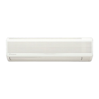
Wall-mounted type
FXAQ20MAVE
FXAQ25MAVE
FXAQ32MAVE
FXAQ40MAVE
FXAQ50MAVE
FXAQ63MAVE
SYSTEM Inverter Air Conditioners
INSTALLATION MANUAL
READ THESE INSTRUCTIONS CAREFULLY BEFORE INSTALLATION.
KEEP THIS MANUAL IN A HANDY PLACE FOR FUTURE REFERENCE.
LESEN SIE DIESE ANWEISUNGEN VOR DER INSTALLATION SORGFÄLTIG DURCH.
BEWAHREN SIE DIESE ANLEITUNG FÜR SPÄTERE BEZUGNAHME GRIFFBEREIT AUF.
LIRE SOIGNEUSEMENT CES INSTRUCTIONS AVANT L’INSTALLATION.
CONSERVER CE MANUEL A PORTEE DE MAIN POUR REFERENCE ULTERIEURE.
LEA CUIDADOSAMENTE ESTAS INSTRUCCIONES ANTES DE INSTALAR.
GUARDE ESTE MANUAL EN UN LUGAR A MANO PARA LEER EN CASO DE TENER
ALGUNA DUDA.
PRIMA DELL’INSTALLAZIONE LEGGERE ATTENTAMENTE QUESTE ISTRUZIONI.
TENERE QUESTO MANUALE A PORTATA DI MANO PER RIFERIMENTI FUTURI.
ÄΙΑΒΑΣΤΕ ΠΡΟΣΕΚΤΙΚΑ ΑΥΤΕΣ ΤΙΣ ΟÄΗΓΙΕΣ ΠΡΙΝ ΑΠΟ ΤΗΝ ΕΓΚΑΤΑΣΤΑΣΗ ΕΧΕΤΕ ΑΥΤΟ
ΤΟ ΕΓΧΕΙΡΙÄΙΟ ΕΥΚΑΙΡΟ ΓΙΑ ΝΑ ΤΟ ΣΥΜΒΟΥΛΕΥΕΣΤΕ ΣΤΟ ΜΕΛΛΟΝ.
LEES DEZE INSTRUCTIES ZORGVULDIG DOOR VOOR INSTALLATIE. BEWAAR DEZE HAN-
DLEINDING WAAR U HEM KUNT TERUGVINDEN VOOR LATERE NASLAG.
LEIA COM ATENÇÃO ESTAS INSTRUÇÕES ANTES DE REALIZAR A INSTALAÇÃO.
MANTENHA ESTE MANUAL AO SEU ALCANCE PARA FUTURAS CONSULTAS.
ПЕРЕД НАЧАЛОМ МОНТАЖА ВНИМАТЕЛЬНО ОЗНАКОМЬТЕСЬ С ДАННЫМИ
ИНСТРУКЦИЯМИ. СОХРАНИТЕ ДАННОЕ РУКОВОДСТВО В МЕСТЕ, УДОБНОМ ДЛЯ
ОБРАЩЕНИЯ В БУДУЩЕМ.
00_CV_3P156215-10P.fm Page 1 Friday, March 28, 2008 2:21 PM
Question and Answer IconNeed help?

Do you have a question about the Daikin VRV FXAQ63MAVE and is the answer not in the manual?

Daikin VRV FXAQ63MAVE Specifications

General IconGeneral
Model NumberFXAQ63MAVE
SeriesVRV
Cooling Capacity6.3 kW
Heating Capacity7.1 kW
Power Supply220-240 V, 50 Hz
Weight13 kg
RefrigerantR410A

Summary

Safety Considerations

Meaning of Warning and Caution Symbols

Explanation of symbols used to indicate warnings and cautions in the manual.

Before Installation

2-1 Precautions

Important warnings and precautions to be observed prior to installation.

2-2 Accessories

List of standard accessories included with the indoor unit for installation.

2-3 Optional Accessories

Details on optional accessories available for enhancing unit functionality and control.

2-4 Note to the Installer

Specific instructions and advice for the installation technician.

Selecting Installation Site

Indoor Unit Installation

Open the Piping Through-hole

Procedure for creating the necessary opening in the wall for piping.

Attach the Installation Panel to the Wall

Instructions for mounting the installation panel securely on the wall.

Prepare the Front Grill for Piping

Cutting the front grill to accommodate different piping exit directions.

Remove Front Panel and Service Lid

Steps for accessing internal components by removing the front panel and service lid.

Route Piping and Wiring

Guiding refrigerant piping, drain hose, and electrical wiring.

Secure the Indoor Unit to the Installation Panel

Final step to firmly attach the indoor unit to the wall panel.

Refrigerant Piping Work

Drain Piping Work

Install the Drain Piping

Guidelines for installing the drain pipe to ensure correct slope and flow.

Make Sure the Drain Works Properly

Performing a check to verify the proper functioning of the drain system.

Electric Wiring Work

7-1 General Instructions

General guidelines and requirements for electrical wiring.

7-2 Electrical Characteristics

Technical specifications related to the electrical characteristics of the unit.

7-3 Specifications for Field Supplied Fuses and Wire

Specifications for fuses and wiring materials to be supplied by the installer.

How to Connect Wirings and Wiring Example

8-1 How to Connect Wirings

Step-by-step methods for connecting power supply, unit, and remote controller wirings.

Wiring Precautions and Terminal Connections

Essential wiring practices, terminal usage, torque specifications, and safety warnings.

8-2 Wiring Example

Illustrative examples of different wiring configurations for the system.

Field Settings

9-1 Setting Air Filter Sign

Configuring the air filter cleaning indicator based on room dust levels.

9-2 Setting Air Flowrate Increase Mode

Adjusting settings to increase or decrease the air flow rate.

9-3 Control by 2 Remote Controllers

Instructions for operating a single indoor unit with two remote controllers.

Main/Sub Changeover

Switching between main and sub roles for dual remote controller operation.

9-4 Computerised Control (Forced Off and On/Off Operation)

Methods for controlling unit operations via external signals like forced off.

External Control Wiring and Operation Selection

Wiring specifications and procedure to select FORCED OFF or ON/OFF operation.

9-5 Centralized Control

Guidelines for setting up and managing centralized control systems.

Test Operation

Related product manuals