EasyManua.ls Logo

Daikin VRV FXMQ24PBVJU - User Manual

Daikin VRV FXMQ24PBVJU
18 pages
Print Icon
To Next Page IconTo Next Page
Loading...
English
Français
Español
SYSTEM Inverter Air Conditioners
INSTALLATION MANUAL
MODELS
Ceiling-mounted Duct type
FXMQ07PBVJU FXMQ24PBVJU
FXMQ09PBVJU FXMQ30PBVJU
FXMQ12PBVJU FXMQ36PBVJU
FXMQ15PBVJU FXMQ48PBVJU
FXMQ18PBVJU FXMQ54PBVJU
READ THESE INSTRUCTIONS CAREFULLY BEFORE INSTALLATION.
KEEP THIS MANUAL IN A HANDY PLACE FOR FUTURE REFERENCE.
LIRE SOIGNEUSEMENT CES INSTRUCTIONS AVANT L’INSTALLATION.
CONSERVER CE MANUEL A PORTEE DE MAIN POUR REFERENCE ULTERIEURE.
LEA CUIDADOSAMENTE ESTAS INSTRUCCIONES ANTES DE INSTALAR.
GUARDE ESTE MANUAL EN UN LUGAR A MANO PARA LEER EN CASO DE TENER ALGUNA
DUDA.
00_CV_3PN14093-18K.fm Page 1 Tuesday, December 9, 2014 11:27 AM
Question and Answer IconNeed help?

Do you have a question about the Daikin VRV FXMQ24PBVJU and is the answer not in the manual?

Summary

Safety Considerations

General Safety Precautions

Essential safety guidelines, warnings, and cautions for installation and operation.

Symbol Meanings

Explanations of DANGER, WARNING, CAUTION, and NOTE symbols used in the manual.

Before Installation

Unit Handling and Site Precautions

Guidance on unit transport, handling, and precautions for specific installation locations and environments.

Installation Best Practices and Accessories

Key installation precautions, including using specified parts, proper air filter mounting, and verifying accessories.

Installation Site Selection

Site Selection Criteria and Customer Guidance

Guidelines for choosing an appropriate installation location and instructing customers on operation.

Preparation and Installation Steps

Site Preparation and Service Space Requirements

Requirements for ceiling openings, service spaces, and hanging bolt installation for the indoor unit.

Duct and Wiring Preparation

Steps for preparing canvas ducts, installation holes, and hanging bolts for the unit installation.

Indoor Unit Installation

Securing the Indoor Unit

Step-by-step guide for temporarily installing and securely fixing the indoor unit using hanging brackets.

Drain Pan Protection and Leveling

Warning to protect the drain pan, and steps for adjusting and leveling the unit after installation.

Refrigerant Piping Work

Refrigerant Piping Connection and Tightening

Detailed steps for connecting refrigerant pipes, including flare nut processing and torque specifications.

Refrigerant Piping Precautions and Insulation

Critical cautions regarding R410A refrigerant, tools, oil application, and insulating piping joints.

Drain Piping Work

Drain Piping Installation and Slope Requirements

Guidelines for installing drain piping, ensuring proper slope, and preventing air banks for effective drainage.

Electrical Work Prerequisites

Drain Piping Support and Electrical Work Start

Instructions for supporting drain piping, connecting hoses, and prerequisites for electrical wiring.

Duct Work Installation

Ductwork Installation and Insulation

Procedures for installing ducts, ensuring proper static pressure, insulation, and air filter attachment.

Drain Pump Operation Check and Insulation

Steps to check drain pump operation and insulate components to prevent water leakage after electrical work.

Electric Wiring Work

General Wiring Instructions and Specifications

Guidelines for field wiring, wire types, grounding, and electrical specifications for components.

Electrical Characteristics Data

Table detailing electrical specifications like voltage, MCA, MOP, kW, and FLA for different models.

Wiring Examples and Remote Controller Setup

Wiring Examples for System Configurations

Diagrams illustrating wiring for single and multiple remote controller setups, including BS unit integration.

Power Supply Wiring Precautions

Essential precautions for power supply wiring, terminal connections, and tightening torque values.

Field Setting and Control Operations

Basic Field Setting Procedure

Steps to enter field setting mode and configure basic operational parameters using the remote controller.

Airflow and Static Pressure Settings

How to adjust airflow automatic adjustment and set external static pressure based on duct conditions.

Field Setting and Test Operation

Filter and Drain Pump Settings

Procedures for setting air filter cleaning display intervals and enabling/disabling the drain pump.

Test Operation and Malfunction Checks

Test Run Procedure and Malfunction Identification

Steps for conducting the test operation, checking for malfunctions, and identifying error codes.

Overview

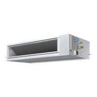
This document is an installation manual for Daikin VRV SYSTEM Inverter Air Conditioners, specifically for ceiling-mounted duct type models.

Function Description:

The Daikin VRV SYSTEM Inverter Air Conditioners are designed for indoor installation, providing heating and cooling functions. These units are part of a VRV (Variable Refrigerant Volume) system, which allows for multiple indoor units to be connected to a single outdoor unit, offering flexible climate control for various spaces. The inverter technology enables precise control over refrigerant flow, leading to improved energy efficiency and consistent temperature management. The manual outlines the procedures for installing these units, including safety considerations, site selection, preparation, indoor unit installation, refrigerant piping, drain piping, duct work, electric wiring, remote controller setup, field settings, and test operation.

Important Technical Specifications:

  • Models Covered: FXMQ07PBVJU, FXMQ09PBVJU, FXMQ12PBVJU, FXMQ15PBVJU, FXMQ18PBVJU, FXMQ24PBVJU, FXMQ30PBVJU, FXMQ36PBVJU, FXMQ48PBVJU, FXMQ54PBVJU.
  • Refrigerant Type: R410A. The system is designed exclusively for R410A refrigerant.
  • Power Supply: Single phase, 60Hz, 208/230V.
  • Field Fuses: 15A.
  • Wiring:
    • Power Supply Wiring: Copper wire only, size and length must comply with local codes.
    • Remote Controller/Transmission Wiring: 2-conductor, stranded non-shielded copper cable (PVC/vinyl jacket), AWG18-16.
    • Allowable Lengths:
      • Outdoor unit - Indoor unit: Max. 3280 ft (1,000 m) (Total wiring length: 6560 ft (2,000 m)).
      • Indoor unit - Remote controller: Max. 1640 ft (500 m)).
  • Drain Piping: Minimum downward slope of 1/100. Connecting pipe (vinyl chloride pipe) with an outer diameter of 1-1/4 in. (32 mm) and a nominal inner diameter of 31/32 in. (25 mm). No drain trap is required.
  • Insulation Material: Must withstand a temperature of 248°F (120°C). For ceiling installations, glass wool or polyethylene foam with a minimum thickness of 3/8 in. (10 mm) is recommended if the temperature above the ceiling exceeds 86°F (30°C) and relative humidity is 80%.
  • Hanging Bolts: M10 size.
  • External Static Pressure Settings: Adjustable via remote controller, with various settings for different models and pressure ranges (e.g., 0.12 inWG (30 Pa) to 0.80 inWG (200 Pa)).
  • Airflow Rate (CFM (m³/min)):
    • 07/09 type: 317 (9.0)
    • 12 type: 450 (12.7)
    • 15 type: 560 (15.8)
    • 18 type: 635 (18.0)
    • 24 type: 688 (19.5)
    • 30 type: 1094 (31.0)
    • 36 type: 1130 (32.0)
    • 48 type: 1377 (39.0)
    • 54 type: 1624 (46.0)

Usage Features:

  • Remote Control: The units can be operated via a wired remote controller (optional wireless kit available). The remote controller allows for setting various operational parameters, including airflow adjustment (HH, H, L), temperature, and special functions like forced off/on.
  • Group Control: The system supports group control, where multiple indoor units can be managed by a single remote controller.
  • Centralized Control: For more complex installations, centralized control is possible, requiring specific group number designations.
  • Airflow Auto Adjustment: The unit can automatically adjust the volume of blow-off air to the rated quantity, which is set during field settings.
  • Drain Pump Operation: The drain pump operation can be enabled or disabled via field settings, allowing for natural drainage if preferred.
  • Computerized Control (Forced Off/On Operation): External input to terminals T1 and T2 allows for forced off or on operation, overriding remote controller commands.

Maintenance Features:

  • Service Space: The manual specifies minimum service spaces for maintenance and inspection of the control box and drain pump, including inspection hatches (17-3/4 in. x 17-3/4 in.) and lower product clearance (12 in.).
  • Filter Sign Settings: The remote controller's LCD displays a filter sign to indicate when air filter cleaning is due. Settings can be adjusted for standard (approx. 2500 hours) or excessive dust conditions (approx. 1250 hours), or disabled.
  • Troubleshooting: The remote controller displays malfunction codes (e.g., U4, UH, A8, C1, C6, U3) to help identify issues such as power supply problems, wiring errors, or communication failures. The manual provides a table of these codes and their corresponding content for diagnosis.
  • Cleaning: The manual emphasizes the importance of cleaning filters and provides instructions for handling and cleaning field supplies.
  • Refrigerant Leakage Check: After installation, it is crucial to check for refrigerant gas leaks throughout the system.
  • Heat Insulation: Proper heat insulation of refrigerant piping is essential to prevent condensation and ensure efficient operation.
  • Drainage Check: After installation, the smooth draining of the piping must be checked to prevent water leakage.

Daikin VRV FXMQ24PBVJU Specifications

General IconGeneral
BrandDaikin
ModelVRV FXMQ24PBVJU
CategoryAir Conditioner
LanguageEnglish

Related product manuals