EasyManua.ls Logo

Daikin VRV FXFSQ25ARV16 - User Manual

Daikin VRV FXFSQ25ARV16
30 pages
Print Icon
To Next Page IconTo Next Page
Loading...
Question and Answer IconNeed help?

Do you have a question about the Daikin VRV FXFSQ25ARV16 and is the answer not in the manual?

Summary

SAFETY PRECAUTIONS

BEFORE INSTALLATION

SPECIAL NOTICE PRODUCT

Important precautions for R410A refrigerant, system cleanliness, and sealing.

ACCESSORIES

Lists all standard accessories included with the indoor unit for installation.

OPTIONAL ACCESSORIES

Details optional accessories like decoration panels and remote controllers.

NOTE TO THE INSTALLER

Provides specific instructions and advice for the installer regarding customer interaction.

SELECTION OF INSTALLATION LOCATION

PREPARATION BEFORE INSTALLATION

INSTALLATION OF INDOOR UNIT

Install the indoor unit temporarily

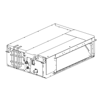
Initial steps to secure the indoor unit, including fixing hangers.

Make the ceiling opening

Instructions for creating the necessary opening in the ceiling for unit installation.

Install hanging bolts

Guidance on securely installing hanging bolts to support the indoor unit.

Check unit level and remove clamps

Procedures for leveling the unit and removing temporary clamps after installation.

REFRIGERANT PIPING WORK

Gas side piping insulating method

Method for insulating gas side piping to prevent condensation and ensure safety.

Liquid side piping insulating method

Method for insulating liquid side piping to prevent condensation and ensure safety.

DRAIN PIPING WORK

ELECTRIC WIRING WORK

GENERAL INSTRUCTIONS

General guidelines for performing electrical wiring work safely and correctly.

ELECTRICAL CHARACTERISTICS

Technical specifications for electrical components and power requirements.

SPECIFICATION FOR FIELD SUPPLY FUSES AND WIRING

Details on required fuses, wiring types, and sizes for field supply.

WIRING CONNECTION METHOD

Step-by-step guide for connecting power, remote, and transmission wiring.

EXAMPLE OF WIRING

Illustrates common wiring configurations for indoor units.

FOR CONTROL WITH 2 REMOTE CONTROLLERS

Instructions for setting up control for one indoor unit with two remote controllers.

MOUNTING DECORATION PANEL

FIELD SETTING AND TEST OPERATION

FIELD SETTING

Procedures for configuring unit settings based on installation conditions.

TEST OPERATION

Steps to perform after installation to verify unit functionality.

SETTING CEILING HEIGHT

How to set the ceiling height parameter for optimal sensor operation.

SETTING AIR DISCHARGE DIRECTION

Adjusting the direction of air discharge using sealing materials and settings.

SETTING WHEN AN OPTIONAL ACCESSORY IS ATTACHED

Guidance for setting up the unit with optional accessories.

WHEN USING WIRELESS REMOTE CONTROLLER

Instructions for setting up a wireless remote controller address.

SETTING FAN SPEED DURING THERMOSTAT OFF

How to adjust fan speed when the thermostat is off, based on customer consultation.

SETTING FILTER SIGN

Setting the filter cleaning notification based on room contamination levels.

Overview

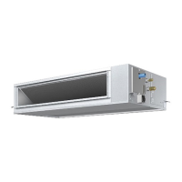
This document serves as both an Installation Manual and an Operation Manual for Daikin VRV System Air Conditioners, specifically the Ceiling Mounted Cassette type (New Sensing Flow Model).

Function Description

The Daikin VRV System Air Conditioner is designed for indoor use, providing cooling and heating functions for various environments. The "New Sensing Flow Model" indicates advanced sensing capabilities, likely related to airflow and temperature distribution, to optimize comfort and energy efficiency. The system is designed for installation in a machine room free of moisture and is intended for commercial or public spaces rather than domestic use, as indicated by its classification as a Class A product that may cause radio interference in a domestic environment.

The unit features a built-in drain discharge device to remove indoor moisture during cooling operation and includes an infrared presence sensor and an infrared floor sensor to detect occupancy and average floor temperature, respectively. These sensors likely contribute to the "New Sensing Flow" capabilities, allowing the unit to adjust airflow and temperature settings based on real-time environmental conditions and occupancy. The air discharge direction can be adjusted and sealed for 4-way, 3-way, or 2-way blow types, offering flexibility in room layout and airflow optimization.

The system supports various control configurations, including single indoor unit control, group control with multiple indoor units, and control with two remote controllers for a single indoor unit. It also offers centralized control capabilities, allowing integration with centralized control equipment. Remote control functionality includes forced OFF or ON/OFF operation via external input.

Important Technical Specifications

  • Models Covered: FXFSQ25ARV16, FXFSQ32ARV16, FXFSQ40ARV16, FXFSQ50ARV16, FXFSQ63ARV16, FXFSQ80ARV16, FXFSQ100ARV16, FXFSQ125ARV16, FXFSQ140ARV16.
  • Refrigerant: R410A, a fluorinated greenhouse gas with a GWP value of 1975. Strict precautions are required to keep the system clean, dry, and tightly sealed.
  • Design Pressure: 4.0 MPa or 40 bar (for R410A units).
  • Piping Thickness: Must be greater than previously due to R410A's higher design pressure.
  • Refrigerant Charging: Must be charged in its liquid state due to R410A being a mixed refrigerant.
  • Power Supply: Single phase 220-240 V, 50 Hz.
  • Electrical Characteristics (Fan Motor):
    • FXFSQ25-32ARV16: 0.053 kW, 0.2 FLA
    • FXFSQ40ARV16: 0.053 kW, 0.3 FLA
    • FXFSQ50-63ARV16: 0.053 kW, 0.5 FLA
    • FXFSQ80ARV16: 0.053 kW, 0.8 FLA
    • FXFSQ100-140ARV16: 0.106 kW, 1.1-1.4 FLA
  • Power Supply Wiring: H05VV-U3G, 2.5 mm², 16A field fuses.
  • Remote Controller/Transmission Wiring: Vinyl cord with sheath or cable (2 core), 0.75-1.25 mm².
  • Maximum Wiring Lengths:
    • Remote controller (indoor unit): Max. 500 m
    • Transmission wirings (total): 2000 m
    • Outdoor unit - Indoor unit: Max. 1000 m
    • Outdoor unit - BS unit: Max. 1000 m
    • BS unit - Indoor unit: Max. 1000 m
    • Indoor unit - Indoor unit: Max. 1000 m
  • Ceiling Height: Up to 3.5 m (Type 100-140: 4.2 m). Field setting is required if height exceeds 2.7 m (Type 100-140: 3.2 m).
  • Installation Space (Minimum): At least 1500 mm from a floor, and 1500 mm from any fixture. Clearance from the wall must be 500 mm or more if the air outlet is closed or horizontal blade is set to Airflow block, or 200 mm or more if corners are also closed.
  • Drain Piping: Polyvinyl chloride piping, nominal diameter 25 mm (outside diameter 32 mm). Downward inclination of 1/100 or more. Maximum drain riser height is 675 mm, with 300 mm or higher recommended.
  • Hanging Bolts: M8 or M10 bolts for installation.
  • Optional Decoration Panels: BYCQ140EEF6, BYCQ125EAF6, BYCQ125EEK, BYCQ125EAK, BYCQ125EAPF, BYCQ125EASF (available in Fresh white/Black).
  • Remote Controllers: Wired type (BRC1E63) and Wireless type (BRC7M632F-6 for Heat pump, Cooling only).

Usage Features

  • Optimized Air Distribution: The unit allows selection of the number of air discharge directions (all round, 4-way, 3-way, 2-way) to suit room shape and position. Sealing materials can be used to change the discharge direction, with corresponding field settings required via the remote controller.
  • Sensing Capabilities: Infrared presence and floor sensors enable the unit to detect occupancy and floor temperature, allowing for intelligent adjustments to maintain comfort and potentially save energy.
  • Remote Control: Supports both wired and wireless remote controllers for operation, including setting fan speed, temperature, and various functions.
  • Centralized Control Compatibility: Can be integrated with centralized control equipment for managing multiple units.
  • Forced Operation: External input terminals (T1, T2) allow for forced OFF or ON/OFF operation, useful for specific control scenarios.
  • Filter Sign: The remote controller displays a "Time to clean filter" message, indicating when the air filter needs cleaning. The interval for this message can be adjusted based on room contamination levels (Normal: 2500 hours/1 year; More contaminated: 1250 hours/half year).
  • Ceiling Height Adjustment: The unit's operation can be optimized for different ceiling heights through field settings via the remote controller.

Maintenance Features

  • Air Filter Cleaning: The air filter is located inside the suction grille and can be removed for cleaning. It should be cleaned when the remote controller indicates "Time to clean filter." Cleaning involves washing with water and neutral detergent if heavily contaminated, then drying in the shade.
  • Suction Grille Cleaning: The suction grille can be removed and washed with neutral detergent and a soft brush. For extremely contaminated grilles, a detergent for ventilating fans and ranges can be sprayed and left for 10 minutes before washing.
  • Air Outlet, Outside Panel, and Remote Controller Cleaning: These parts can be wiped with a dry soft cloth. For stubborn stains, a cloth dipped in water-diluted neutral detergent can be used, followed by wiping with a dry cloth.
  • Periodical Inspections: Periodical inspections for refrigerant leakage may be required depending on local legislation.
  • Qualified Personnel Requirement: All installation, modification, repair, and maintenance work, especially electrical wiring and refrigerant handling, must be carried out by qualified personnel to prevent water leakage, electric shocks, fire, or malfunction.
  • Safety Precautions: The manual emphasizes disconnecting the power supply before touching electrical components, earthing the unit, and using specified parts and accessories for installation. It also warns against using flammable gases or solvents near the unit and advises immediate ventilation in case of refrigerant leaks.
  • Drainage Check: After installation, the drain flow must be checked by pouring water into the drain pan and observing smooth drainage during test operation.
  • Insulation: Refrigerant piping and drain piping must be securely insulated to prevent condensation and water leakage.
  • Filter Replacement: If the air filter becomes difficult to clean, it can be replaced with an optional accessory.

Daikin VRV FXFSQ25ARV16 Specifications

General IconGeneral
BrandDaikin
ModelVRV FXFSQ25ARV16
CategoryAir Conditioner
LanguageEnglish

Related product manuals