18 | Electrical installation
Installer and user reference guide
103
RKXYQ5T8+8T7Y1B + RDXYQ5T8+8T7V1B
VRV IV heat pump for indoor installation
4P499898-1A – 2020.10
b Power supply
c Cable tie
5 Reattach the service covers. See "18.5To close the compressor unit"[4105].
6 Connect an earth leakage circuit breaker and fuse to the power supply line.
18.3 To connect the electrical wiring on the heat exchanger unit
NOTICE
▪ Follow the wiring diagram (delivered with the unit, located at the inside of the
service cover).
▪ Make sure the electrical wiring does NOT obstruct proper reattachment of the
service cover.
1 Remove the service cover. See "To open the switch box cover of the heat
exchanger unit"[467].
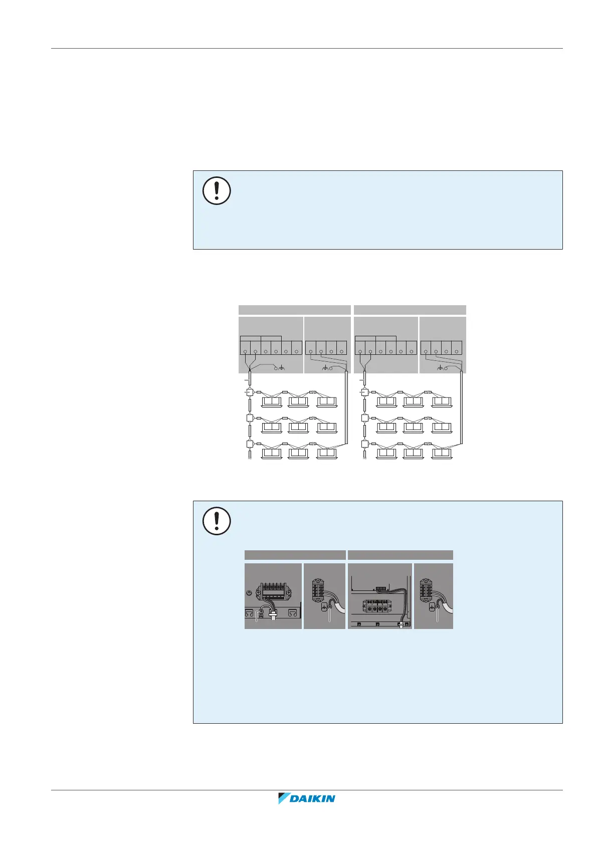
2 Connect the transmission wiring as follows:
F1 F2 F1 F2 F1 F2
F1 F2 F1 F2 F1 F2
F1 F2 F1 F2 F1 F2
b
X2M
X2M
X2M X1M (A1P)
RKXYQ5 RDXYQ5
TO OUT/DTO IN/D
F1 F2
F1 F2
a1 a2 a2
a
F1 F2 F1 F2 F1 F2
F1 F2 F1 F2 F1 F2
F1 F2 F1 F2 F1 F2
b
a
RKXYQ8 RDXYQ8
TO OUT/DTO IN/D
F1 F2
F1 F2
8 HP5 HP
a Sheathed + shielded cable (2 wires) (no polarity)
a1, a2 Connection of shield to earth
b Terminal board (field supply)
NOTICE
Shielded cable. Using shielded cable for the transmission wiring is mandatory for
5HP, and optional for 8HP.
X2M
F1 F2
F1 F2
a1
X1M
X1M (A1P)
5 HP 8 HP
X2M
a2
F1 F2
X2M
a2
F1 F2
RKXYQ5 RDXYQ5 RKXYQ8 RDXYQ8
a1, a2 Earth (use the screw delivered as accessory)
When using shielded cable:
▪ In case of 5HP (a1 and a2): Connect the shield to the earth of the compressor
unit and the heat exchanger unit.
▪ In case of 8 HP (only a2): Connect the shield only to the earth of the heat
exchanger unit.
3 Connect the power supply as follows:
 Loading...