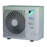
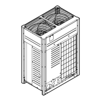
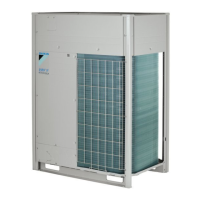
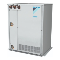
1.3. Indoor capacity range
6QVCNECRCEKV[QHKPFQQTWPKVUPGGFUVQDGYKVJKPVJGURGEKƂGFTCPIG
<Outdoor unit> 6QVCNECRCEKV[KPFGZQHKPFQQTWPKV
RXYQ72TTJU/TYDN . . . . . . . . . . . . . . . . . . . . . 36-93
RXYQ96TTJU/TYDN . . . . . . . . . . . . . . . . . . . . . 48-124
RXYQ120TTJU/TYDN . . . . . . . . . . . . . . . . . . . . . 60-156
RXYQ144TTJU/TYDN . . . . . . . . . . . . . . . . . . . . . 72-187
RXYQ168TTJU/TYDN . . . . . . . . . . . . . . . . . . . . . 84-218
RXYQ192TTJU/TYDN . . . . . . . . . . . . . . . . . . . . . 96-249
RXYQ216TTJU/TYDN . . . . . . . . . . . . . . . . . . . . . 108-280
RXYQ240TTJU/TYDN . . . . . . . . . . . . . . . . . . . . . 120-312
RXYQ264TTJU/TYDN . . . . . . . . . . . . . . . . . . . . . 132-343
RXYQ288TTJU/TYDN . . . . . . . . . . . . . . . . . . . . . 144-374
RXYQ312TTJU/TYDN . . . . . . . . . . . . . . . . . . . . . 156-405
RXYQ336TTJU/TYDN . . . . . . . . . . . . . . . . . . . . . 168-436
RXYQ360TTJU/TYDN . . . . . . . . . . . . . . . . . . . . . 180-468
RXYQ384TTJU/TYDN . . . . . . . . . . . . . . . . . . . . . 192-499
RXYQ408TTJU/TYDN . . . . . . . . . . . . . . . . . . . . . 204-530
NOTE
Higher capacity than the above table can be selected, this may affect
heating and cooling capacity. For additional information see technical
engineering data.
1.4. Scope of the manual
This manual describes the procedures for handling, installing and
connecting the VRV IV heat pump outdoor units. This manual has
been prepared to ensure adequate maintenance of the unit, and it will
provide help in case problems occur.
INFORMATION
The installation of the indoor unit(s) is described in the indoor unit
installation manual provided with the indoor units.
2. Accessories
2.1. Accessories supplied with this unit
%QPƂTOVJGHQNNQYKPICEEGUUQTKGUCTGKPENWFGF6JGUVQTCIGNQECVKQP
QHVJGCEEGUUQTKGUKUUJQYPKPVJGƂIWTGDGNQY
Accessories assy (piping)
Accessories assy (operation
and installation manual)
NOTE
Do not throw away any of the accessories until installation is complete.
They are needed for installation work.
Name Clamp(1) Clamp(2) Vinyl tube Manuals, etc.
Quantity 7 pcs. 1 pc. 5 pcs. 1 pc. each
Shape
(Small)
(Large)
r Operation Manual
r Installation Manual
r 4'37'56(146*'
INDICATON label
(Installation records)
Name
Liquid side
accessory
pipe (1)
Liquid side
accessory
pipe (2)
Gas side
accessory
pipe (1)
Gas side
accessory
pipe (2)
L type
accessory
joint
Quantity 1 pc. 1 pc. 1 pc. 1 pc. 1 pc.
Shape
72-96T
120-168T
120-168T
3. Overview of unit
3.1. Opening the unit
To gain access to the unit, front panels need to be opened as follows:
RXYQ72TTJU/TYDN RXYQ96-168TTJU/TYDN
14x14x
1PEGVJGHTQPVRCPGNQRGPVJGGNGEVTKECNEQORQPGPVDQZECPDGCE-
EGUUGFD[TGOQXKPIVJGEQPVTQNDQZEQXGTCUHQNNQYU
RXYQ72TTJU/TYDN RXYQ96-168TTJU/TYDN
2x
6x
For service purposes, the push buttons on the main printed circuit
board need to be accessed. To access these push buttons, the control
DQZEQXGTFQGUPQVPGGFVQDGQRGPGF5GG/CMKPIƂGNFUGVVKPIU
QPRCIG|
DANGER: ELECTRICAL SHOCK
5GG5CHGV[EQPUKFGTCVKQPUQPRCIG|K
DANGER: DO NOT TOUCH PIPING AND INTERNAL PARTS
5GG5CHGV[EQPUKFGTCVKQPUQPRCIG|K
 Loading...
