Do you have a question about the Daikin VRV IV RXYQ TYDN Series and is the answer not in the manual?
| Brand | Daikin |
|---|---|
| Model | VRV IV RXYQ TYDN Series |
| Category | Air Conditioner |
| Language | English |
Center of gravity details for RXYQ-TYDN units.
Center of gravity details for RXYQ-TTJU units.
Specific installation notes for RXYQ-TYDN/TTJU models.
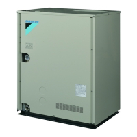
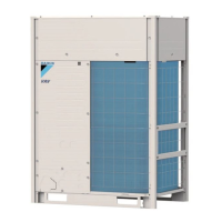
General description of the VRV IV heat pump system.
Information on unit combinations and available options.
Specifies indoor unit capacity limits for outdoor units.
Outlines what the manual covers.
Details of included accessories.
Instructions on how to access internal components.
General site selection criteria and precautions.
Precautions regarding weather conditions at the installation site.
Specific advice for installing in cold weather environments.
Provides physical dimensions and mounting hole details.
Details required clearances for maintenance and airflow.
How to check the unit upon delivery for damage.
Safe methods for moving and transporting the unit.
Steps for safely removing the unit from its packaging.
Basic requirements for unit placement and leveling.
Instructions for removing protective shipping components.
Important notes regarding R410A refrigerant handling.
Specifies approved materials for refrigerant piping.
Provides tables for selecting correct pipe diameters.
Piping size selection for connecting to BP units.
Piping size selection for BP to mini-split units.
Piping size selection for branch kits to indoor units.
Guidance on choosing appropriate REFNET kits.
Specifies maximum allowable lengths for piping systems.
Details on length limitations for system piping.
Piping length limitations for systems with only VRV indoor units.
Piping limitations for mixed VRV and mini-split systems.
Restrictions on piping length after a branch point.
Specific safety advice for brazing refrigerant pipes.
Steps for connecting refrigerant pipes.
Options for pipe connection entry points.
Procedure for removing pinched refrigerant pipes.
Instructions for connecting pipes to the outdoor unit.
Safety guidelines for multi-unit piping connections.
Diagrams showing valid and invalid piping arrangements.
Instructions for installing refrigerant branch kits.
Safety procedures for operating stop valves.
Specific warnings related to stop valve operation.
Step-by-step instructions for opening and closing stop valves.
Warnings about protecting the stop valve cover.
Precautions for using the service port.
Specifications for torque values for valve covers and ports.
Requirements for power supply, safety devices, and cables.
Illustrative wiring diagrams for the entire system.
How to route power and transmission wiring.
Step-by-step instructions for transmission wiring.
Step-by-step instructions for power wiring.
Instructions for wiring connections within indoor units.
Details on airtight testing and vacuum drying process.
Importance of insulating pipes to prevent leaks or burns.
How to access the unit's control buttons.
Instructions for using control buttons and switches.
How to use the unit's push buttons for settings and operations.
Guide to configuring unit settings using DIP switches.
Instructions for connecting a PC for configuration.
Safety warnings before charging refrigerant.
How to determine the amount of refrigerant needed.
Formula and method for calculating extra refrigerant.
Describes methods for adding refrigerant.
Visual guide for refrigerant charging procedures.
Details automatic and manual refrigerant charging methods.
Pre-startup checks to ensure proper installation.
How to operate the unit after installation.
Using Mode 1 for monitoring unit status and basic settings.
Using Mode 2 for field settings and system configuration.
Procedures for verifying correct operation after installation.
Safety measures before performing a test run.
Step-by-step guide for performing the system test run.
How to resolve issues found during the test run.
Further details on malfunction codes and corrective actions.
Overview of maintenance requirements.
Safety warnings for performing service on the unit.
How to use service modes for maintenance tasks.
Steps for evacuating the refrigerant system.
Procedure for safely recovering refrigerant.
Importance of safety standards for refrigerant handling.
Information on checking maximum refrigerant concentration levels.
Illustrates various REFNET piping configurations.
Specific layout examples for heat pump systems.
Tables showing equivalent piping lengths for joints and headers.
Information and diagrams for REFNET joints.
Information and diagrams for REFNET headers.
Diagrams and specifications for REFNET joints.
Diagrams and specifications for REFNET headers.
Specifics for the BHFP22P100U kit.
Installation procedures and examples for the BHFP22P100U kit.
Connection of gas/equalizer pipes and front installation examples.
Connecting REFNET joints and headers for BHFP22P151U.
Safety measures for service personnel working inside the control box.
Safety measures inside the control box and for removing covers.
Proper procedures for lifting the unit safely.
Safe practices for forklift transport.
Safety requirements for electrical installation.
Proper procedures for lifting the unit safely.
Safe practices for forklift transport.
Safety requirements for electrical installation.
