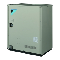
X27A
1
2
3
2
345
H JST
X27A
A1P
1 PC
2 %CDNG'-2%%#$
3 Outdoor unit main printed circuit board
14. Charging refrigerant
14.1. Precautions
NOTE
r 4GHTKIGTCPVECPPQVDGEJCTIGFWPVKNƂGNFYKTKPIJCUDGGPEQO-
pleted.
r Refrigerant may only be charged after performing the leak test and
the vacuum drying.
r 9JGPEJCTIKPICU[UVGOECTGUJCNNDGVCMGPVJCVKVUOCZKOWO
RGTOKUUKDNGEJCTIGKUPGXGTGZEGGFGFKPXKGYQHVJGFCPIGTQH
liquid hammer.
r %JCTIKPIYKVJCPWPUWKVCDNGUWDUVCPEGOC[ECWUGGZRNQUKQPUCPF
accidents, so always ensure that the appropriate refrigerant R410A
is charged.
r Refrigerant containers shall be opened slowly.
r Always use protective gloves and protect your eyes when charging
refrigerant.
r When the refrigerant system is to be opened, refrigerant must be
treated according to the applicable legislation.
DANGER
5GG5CHGV[EQPUKFGTCVKQPUQPRCIG|K
r To avoid compressor breakdown. Do not charge the refrigerant
OQTGVJCPVJGURGEKƂGFCOQWPV
r This outdoor unit is factory charged with refrigerant and depending
on pipe sizes and pipe lengths some systems require additional
charging of refrigerant. See 14.2. Calculating the additional refriger-
ant charge.
r In case recharge is required, refer to the nameplate of the unit.
It states the type of refrigerant and necessary amount.
14.2. Calculating the additional refrigerant charge
NOTE
The refrigerant charge of the system must be less than 210 lbs.
(100 kg). This means that in case the calculated total refrigerant
charge is equal to or more than 209 lbs. (95 kg) you must divide your
multiple outdoor system into smaller independent systems, each
containing less than 209 lbs. (95 kg) refrigerant charge. For factory
charge, refer to the unit nameplate.
14.2.1. How to calculate the additional refrigerant to be charged
Additional refrigerant to be charged=R (lbs.). R should be rounded off
in units of 0.1 lbs.
R=[(X
1
uI
7/8)
u
0.249+(X
2
uI
3/4)
u
0.175+(X
3
uI
5/8)
u
0.121+(X
4
uI
1/2)
u
0.081+(X
5
uI
3/8)
u
0.040+(X
6
uI
1/4)
u
0.015]+[A]+[B]
X
1...6
=Total length (ft. (m)) of liquid piping size at Øa
+PWPKVUQHMICFFKVKQPCNTGHTKIGTCPVVQDGEJCTIGF4MI
R=[(X
1
uI
22.2)
u
0.37+(X
2
uI
19.1)
u
0.26+(X
3
uI
15.9)
u
0.18+(X
4
uI
12.7)
u
0.12+(X
5
uI
9.5)
u
0.059+(X
6
uI
6.4)
u
0.022]+[A]+[B]
Parameter [A]
The amount of refrigerant by the module
Outdoor unit capacity type The amount of refrigerant
RXYQ 72-120T type
0.0 lbs. (0.0 kg)
RXYQ 144T type
8.8 lbs. (4.0 kg)
RXYQ 168T type
9.9 lbs. (4.5 kg)
Parameter [B]
Total indoor
unit capacity
CR
C
RXYQ
72T 96 - 168T
Piping length
ŰHVO
>
105%
1.10 lbs. (0.5 kg)
Piping length
> 98 ft. (30 m)
%4Ű
0.66 lbs. (0.3 kg) 1.10 lbs. (0.5 kg)
%4Ű
1.54 lbs. (0.7 kg) 2.20 lbs. (1.0 kg)
>
105%
2.65 lbs. (1.2 kg) 3.31 lbs. (1.5 kg)
'ZCORNGHQTTGHTKIGTCPVDTCPEJWUKPI4'(0'6LQKPVCPF4'(0'6
JGCFGTHQTU[UVGOUCPFGCEJRKRGNGPIVJCUUJQYPDGNQY'ZCORNG
5[UVGOQPN[EQPVCKPKPI848KPFQQTWPKVUQPRCIG|
Outdoor system: RXYQ264TTJU (RXYQ144TTJU + RXYQ120TTJU)
Total capacity of indoor unit: 116%
a:
I
3/4 × 60 ft.
e: I3/8 × 15 ft. i: I1/2 × 20 ft. s: I1/2 × 15 ft.
b:
I
5/8 × 15 ft.
f: I3/8 × 15 ft. j: I3/8 × 20 ft.
c:
I
3/8 × 15 ft.
g: I1/4 × 15 ft. k: I3/8 × 20 ft.
d:
I
3/8 × 15 ft.
h: I1/4 × 30 ft. r: I1/2 × 10 ft.
R= (
60×0.175
+
15×0.121
+
45×0.081
+
100×0.040
+
45×0.015
) +
8.8
+
3.31+3.31
n
a
n
b
n
i, r, s
n
c, d, e, f, j, k
n
g, h
n
RXYQ144TTJU
n
116%
= 36.055
36.0
lbs.
Round off in units of 0.1 lbs.
INFORMATION
r When using multi models, add the sum of individual capacity types.
r Piping length is considered the distance from the outdoor unit to the
farthest indoor unit.
When selecting indoor unit, following table with connection ratio limita-
tion has to be respected. More detailed information can be found in
'PIKPGGTKPI&CVC$QQM
Used indoor
units
Total capacity
CR
C
Allowable capacity connection ratio
VRV Mini-split
VRV 50 – 200% 50 – 200% –
VRV + Mini-split 80 –130% 0 – 130% 0 – 130%
Mini-split 80 –130% – 80 – 130%
 Loading...
