63P362438-7J English
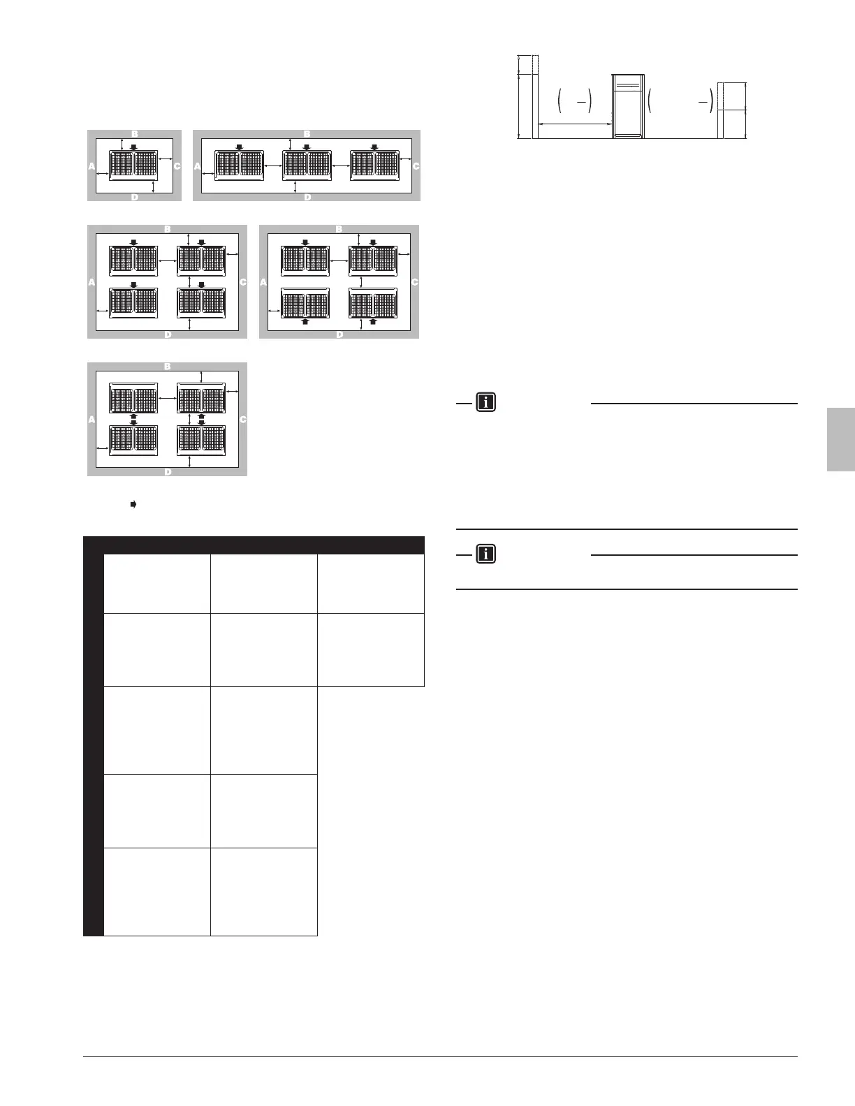
5.2. Service space
The space around the unit is adequate for servicing and the minimum
space for air inlet and air outlet is available (refer to the gure below
and choose one of the possibilities).
a
b
a
c
d
a
b
a
e
d
e
c
a
b
a
e
d
f
c
a
b
a
e
b
d
c
a
b
a
e
d
f
c
3
5
4
ABCD Sides along the installation site with obstacles
Suction side
A+B+C+D A+B
1
a≥3/8 (10)
b≥11-3/4 (300)
c≥3/8 (10)
d≥19-5/8 (500)
a≥2 (50)
b≥3-7/8 (100)
c≥2 (50)
d≥19-5/8 (500)
a≥7-7/8 (200)
b≥11-3/4 (300)
2
a≥3/8 (10)
b≥11-3/4 (300)
c≥3/8 (10)
d≥19-5/8 (500)
e≥3/4 (20)
a≥2 (50)
b≥3-7/8 (100)
c≥2 (50)
d≥19-5/8 (500)
e≥3-7/8 (100)
a≥7-7/8 (200)
b≥11-3/4 (300)
e≥15-3/4 (400)
3
a≥3/8 (10)
b≥11-3/4 (300)
c≥3/8 (10)
d≥19-5/8 (500)
e≥3/4 (20)
f≥23-5/8 (100)
a≥2 (50)
b≥3-7/8 (100)
c≥2 (50)
d≥19-5/8 (500)
e≥3-7/8 (100)
f≥19-5/8 (500)
Unit: in.(mm)
4
a≥3/8 (10)
b≥11-3/4 (300)
c≥3/8 (10)
d≥19-5/8 (500)
e≥3/4 (20)
a≥2 (50)
b≥3-7/8 (100)
c≥2 (50)
d≥19-5/8 (500)
e≥3-7/8 (100)
5
a≥3/8 (10)
b≥19-5/8 (500)
c≥3/8 (10)
d≥19-5/8 (500)
e≥3/4 (20)
f≥35-7/16 (900)
a≥2 (50)
b≥19-5/8 (500)
c≥2 (50)
d≥19-5/8 (500)
e≥3-7/8 (100)
f≥23-5/8 (600)
h2
a
<Front side> <Suction side>
b +
h2
2
or more
Service
space
h1
2
or more
h1
b
+
a 59 in. (1500 mm)
b 19-5/8 in. (500 mm)
• In case of an installation site where sides A+B+C+D have obsta-
cles, the wall heights of sides A+C have no impact on service space
dimensions. Refer to the foregoing gure for impact of wall heights
of sides B+D on service space dimensions.
• In case of an installation site where only the sides A+B have ob-
stacles, the wall heights have no inuence on any indicated service
space dimensions.
• The installation space required on these drawings are for full load
heating operation without considering possible ice accumulation.
If the location of the installation is in a cold climate, then all dimen-
sions above should be >19-5/8 in. (500 mm) to avoid accumulation
of ice in between the outdoor units.
INFORMATION
• The service space dimensions in above gure are based on cooling
operation at 95°F (35°C) ambient temperature (standard condi-
tions).
• If the design outdoor temperature exceeds 95°F (35°C) or the
heat load exceeds maximum capacity in all the outdoor unit, take
an even large space on the intake shown in gure in 5.2. Service
space.
INFORMATION
Further specications can be found in the Engineering Data Book.
01_EN_3P362438-7J.indb 6 11/17/2016 19:13:07