2
• Systems • Installation
13
• Installation
2 Field wiring
2-1 cooling only / heat pump
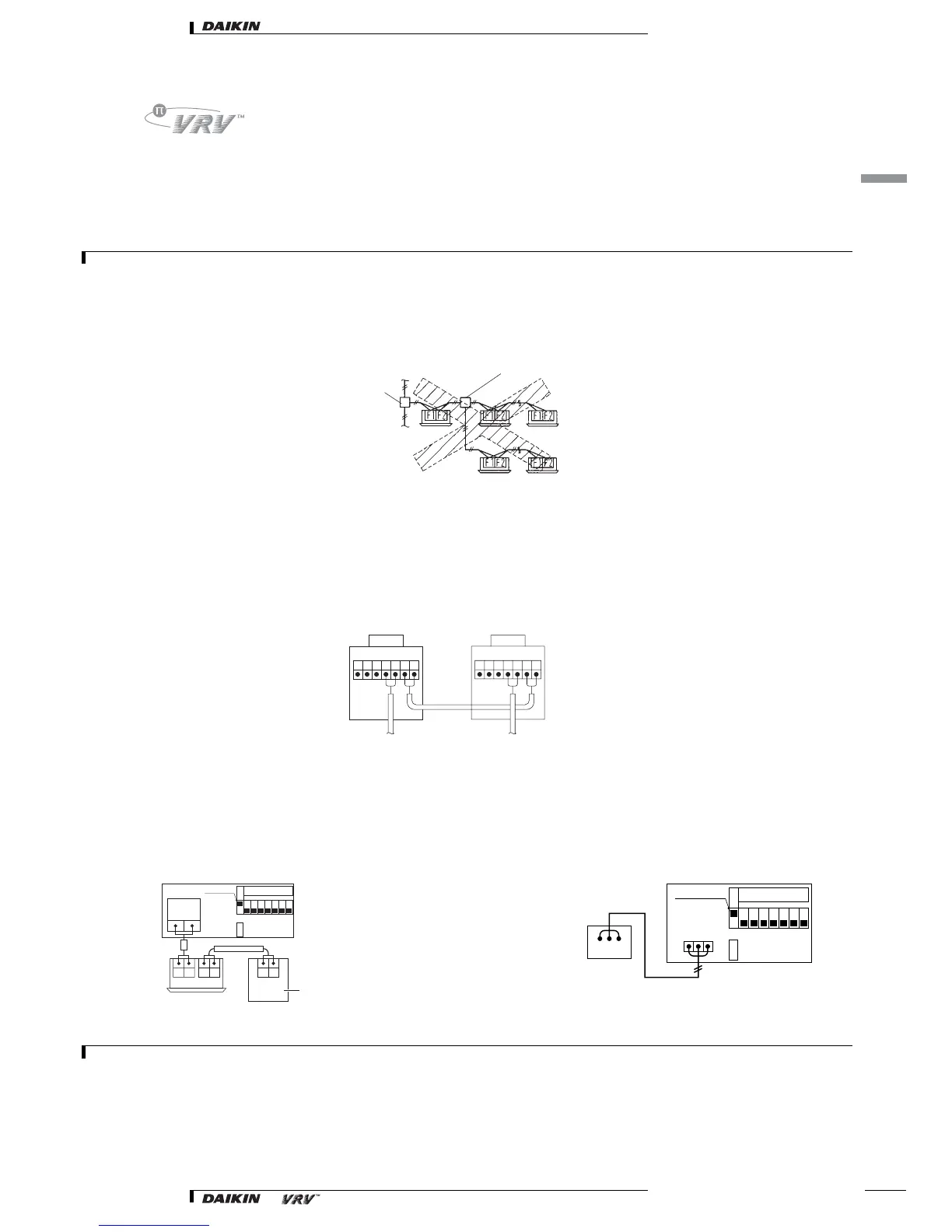
2-1-3 Example of performing cool/heat setting of two or more outdoor units in block with cool/heat selector
•For the wiring shown in front figure, be sure to use 0.75-1.25 mm
2
vinyl cords with sheath or cables (two-core). (Three-core cables can be used only
for the cool/heat selector.)
• The wires above figure are field supply.
CAUTION
1 Be sure to follow the limits below. If the unit-to-unit cables are beyond these limits, it may result in malfunction of transmission.
Maximum wiring length: 1,000m
Total wiring length: 2,000m
Max branches No. of branches: 16
2 Up to 16 branches are possible for unit-to unit cabling. No branching is allowed after branching.
3 Never connect the power supply to unit-to-unit cabling terminal block. Otherwise the entire system may break down.
2-1-4 Sequential start
•Make the outdoor unit cable connections shown below.
• The outdoor unit PC board (A2P) is factory set at “Sequential start available”.
2-1-5 Setting the cool/heat operation
Heat Pump System
1. Performing cool/heat setting with the remote control connected
to the indoor unit.
Keep the cool/heat selector switch (DS1-1) on the outdoor unit PC
board (A2P) at the factory setting position IN/D UNIT.
2. Connect the optional remote control for COOL/HEAT changeover
to the outdoor unit printed circuit board (PCB) (A2P) and change
the COOL/HEAT setting switch (DS1-1) from IN (factory set) to
out.
CAUTION
1For low-noise operation, it is necessary to get the optional “External control adapter for outdoor unit”.
2For details, see the installation manual attached to the adapter.
Branch
Subbranching
(V1313)
ABCF1 F1F2 F2 ABCF1 F1F2 F2
A2P A2P
lndoor unit lndoor unit
(V1314)
TO IN/D
UNIT
F1 F2
C/H SELECTOR
F1 F2 F1 F2
F1 F2
Remote control
(V1315)
O
U
I
N
12345678
ON
OFF
DS1-1 Switch
DS1
A B C
A B C
COOL/HEAT
selector
(V1316)
C/H SELECTOR
O
U
T
I
N
12345678
ON
OFF
DS1-1 Switch
DS1