Do you have a question about the Daikin VRV S RXQ4/5ARV1 and is the answer not in the manual?
Crucial warnings for safe operation and maintenance.
Explanation of symbols used in the manual for clarity.
Records changes made to the manual across different versions.
Identifies various outdoor and indoor unit series and their capacities.
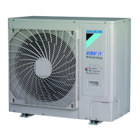
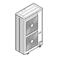
Visual overview of outdoor and indoor unit designs.
Details connection ratios and combinations for outdoor and indoor units.
Technical data for outdoor units, including power, capacity, dimensions, and components.
Illustrates the refrigerant flow and components for various outdoor units.
Diagrams showing the location of key components within outdoor units.
Lists indoor unit series compatible with specific wired and wireless controllers.
Details the buttons and displays of the BRC1E63 and BRC4M Series remote controllers.
Procedures for setting wired remote controllers as main or sub units.
Steps for setting receiver and remote controller addresses for multi-unit operation.
Guides on setting group numbers for centralized control using the BRC1E63.
Accessing service and maintenance data and settings via the remote controller.
Explains operation modes, basic controls, and protection mechanisms for specific outdoor units.
Details operation, startup, protection, and special controls for 6/8 HP outdoor units.
Describes thermostat control, airflow, and other functions for indoor units.
Procedures for changing indoor unit settings via remote controller or PCB.
Guides on setting modes, capacity, and operations for 4/5 HP outdoor units using DIP switches.
Details function settings, DIP switch usage, and mode configurations for 6/8 HP outdoor units.
Instructions for setting capacity and operating modes using BS buttons and DIP switches.
Procedures for initial test operation, power checks, and error code verification.
Steps for pre-operation checks, checkpoints, and test procedures for 6/8 HP units.
Initial checks and precautions for maintenance and troubleshooting.
Guides users through diagnosing issues based on observed system symptoms.
How to read and interpret error codes displayed on the BRC1E63 remote controller.
Lists error codes and their corresponding displays on the outdoor unit PCB for diagnosis.
Detailed descriptions and solutions for various error codes affecting indoor and outdoor units.
Procedures for checking specific components and systems like pressure, superheat, and power transistors.
Electrical diagrams for outdoor units, showing component connections and layouts.
| Model | RXQ4/5ARV1 |
|---|---|
| Cooling Capacity | 4.0 - 5.0 kW |
| Refrigerant | R410A |
| Outdoor Unit Weight | 42 kg |
| Type | VRV |
| Power Supply | 220-240V, 50Hz |
| Outdoor Unit Dimensions (HxWxD) | 320 mm |


