SiAF332111E Check
Part 6 Service Diagnosis 357
6.17 Fan Motor Connector Check (Signal Cable)
CHECK 17 Check the fan motor connector according to the following procedure.
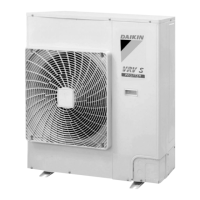
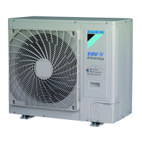
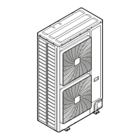
Outdoor Unit RXQ4/5AR
1. Turn OFF the power supply.
2. Remove the connector (X106A) on the PCB to measure the resistance value.
Judgment criteria: resistance value between each phase is within ±20%
Indoor Unit Resistance measuring points and judgment criteria.
FXMQ40PB, FXAQ-P
FXMQ50-140PB
Measurement of signal wire connector.
Remove the X2A connector and measure the resistance between GND and Vcc, Hw, Hv, or Hu
terminals of the motor connector (with five conductors).
White (1)
Orange (2)
Brown (3)
Blue (4)
— (5)
— (6)
Red (7)
FG
Vsp
Vcc
GND
—
—
Vdc
X106A
White (1)
Orange (2)
Brown (3)
Blue (4)
— (
5
)
— (
6)
Red (7)
FG
Vsp
Vcc
GND
—
—
Vdc
Measuring points Judgment criteria
1-4 1 or more
2-4 1 or more
3-4 1 or more
7-4 1 or more
Gray (5)
Pink (4)
Orange (3)
Blue (2)
Yellow (1)
GND
Vcc
Hw
H
V
HU
Connector signal wire use (X2A)

 Loading...


