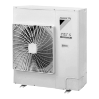
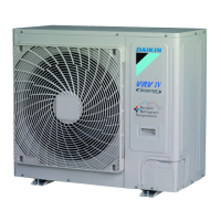
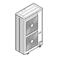
Test Operation (4/5/10/12 HP Models) SiAF332111E
166 Part 5 Field Settings and Test Operation
5.4 Test Operation (10/12 HP Models)
To start smoothly, a crankcase heater is equipped to the unit. To power up the crankcase heater
in advance, be sure to turn on the power supply 6 hours before operation.
Be sure to inform other installers or attach the front panel well before leaving with the power
supply turned on for the outdoor unit. (Raise the front panel as high as possible during
installation to clamp it with the top panel.)
Before powering ON
All indoor units connected with the outdoor unit will operate automatically after powering on.
To ensure safety, ensure that the indoor unit installation has been completed.
Powering ON to Test Operation
Make sure to perform a test operation first after installation (If the unit is operated with the
indoor unit remote controller but without performing a test operation, the error code U3 will
be indicated on the display of the remote controller and the unit will not operate normally).
After turning on the power supply, do not touch any switches excluding button switches and
changeover switches when setting the outdoor unit PCB (A1P).
(For positions of the BS buttons (BS1~3) and changeover switches (DS1-1~4) on the PCB,
refer to the Service Precautions label)
Check the state of the outdoor units and fault wiring with this operation.
(1) Attach the front panel of the outdoor unit.
(2) Turn on the power supply of the outdoor and indoor units.
To power up the crankcase heater in advance, be sure to turn on the power supply 6 hours
before operation.
(3) Remove the front panel of the outdoor unit.
(4) Check LED display of the outdoor unit PCB (A1P), to observe whether data transmission is
normal.
When turning on the power supply: Blinking. Check if the power is up (1-2 minutes) first.
No error: On (8-10 minutes).
Ready: Blank display.
LED display:
Check the LED display of the outdoor unit for error code. If above conditions cannot be
confirmed after 12 minutes, correct relevant error in accordance with the error code.
Communication wiring should be checked first.
Don't touch the switches other than BS buttons and changeover switches of the PCB (A1P)
during setting. Doing so may result in electric shock.
(5) If customer wishes to perform LOW NOISE operation or DEMAND operation, perform setting

 Loading...


