2
• Systems • Installation
29
• Installation
2 Field Wiring
2-4 VRV plus
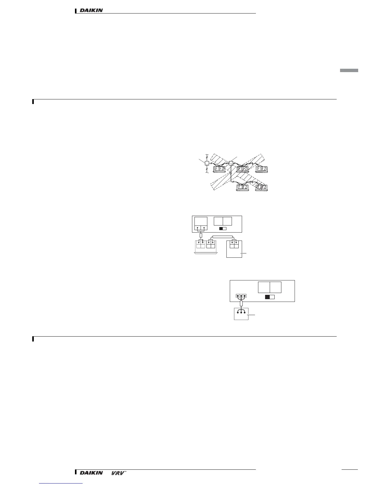
2-4-7 Example of performing cool/heat setting of two or more outdoor units in block with cool/heat selector
•For the wiring shown in figure 22, be sure to use 0.75-1.25 mm
2
vinyl cords with sheath or cables (two-core). (Three-core cables can be used only for
the cool/heat selector.) (Insulated thickness: 1mm or more)
• The wires shown in figure 22 are field supply.
NOTES
Be sure to follow the limits below. If the unit-to-unit cables are beyond these limits, it may result in malfunction of transmission.
Maximum wiring length: 1000m
Total wiring length: 2000m
Max branches No. of branches: 16
Up to 16 branches are possible for unit-to unit cabling. No branching is allowed after branching.
1. Branch
2. Subbranching
Never connect the power supply to unit-to-unit cabling terminal block.
Otherwise the entire system may break down.
2-4-8 Setting the cool/heat operation
1. Performing cool/heat setting with the remote controller connected to
the indoor unit.
Keep the cool/heat selector switch (SS1) on the outdoor unit PC board
(A1P) at the factory setting position IN/D UNIT.
2. Performing cool/heat setting with the cool/heat selector.
Connect the cool/heat selector remote controller (optional) to the A/B/
C terminals and set the cool/heat selector switch (SS1) on the outdoor
unit PC board (A1P) to OUT/D UNIT.
NOTES
For low-noise operation, it is necessary to get the optional “External control adaptor for outdoor unit”.
For details, see the installation manual attached to the adaptor.
1
2
fig.23
fig. 25
TO IN/D
UNIT
F1 F2
IN/D
UNIT
OUT/D
UNIT
SS1
C/H
SELECT
F1 F2 F1 F2
F1 F2
Remote control
IN/D
UNIT
OUT/D
UNIT
SS1
C/H
SELECT
A B C
A B C
Cool/heat selector
fig. 26