Do you have a question about the Dakota Digital 3 Series and is the answer not in the manual?
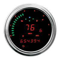
Instructions for mounting universal display systems with ABS subpanels to the dashboard.
Guidance for mounting systems with displays integrated into year-specific aluminum panels.
Steps for installing single lens Dakota Digital systems using plexiglass and aluminum cases.
Installation of complete systems that include a new bezel from Dakota Digital.
Procedure for installing systems with a separate, glue-in lens onto the original bezel.
Mounting instructions for systems where the lens and display are pre-assembled with hardware.
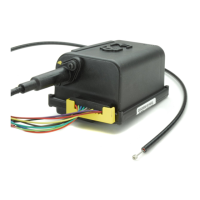
Guidance on selecting a suitable location and method for mounting the control box.
Explanation of control box terminal functions and how to wire them into the vehicle.
Description of the Status LED's function for system diagnostics and operation.
Procedure for selecting and configuring the speed sensor input type for the system.
Instructions for calibrating the speedometer using a measured mile (Auto Cal method).
Method for fine-tuning speedometer calibration by adjusting the signal or using external references.
Guide to setting a distance-based reminder for routine vehicle maintenance.
Configuration for setting the number of engine cylinders to accurately read RPM.
Setting the output signal for auxiliary devices like cruise control or ECM based on speed.
Procedure for selecting the water temperature sensor type and units (Fahrenheit/Celsius).
Setting a high temperature threshold that triggers a visual warning on the display.
Setting a low oil pressure threshold that triggers a visual warning on the display.
Selecting the correct fuel level sender type from pre-programmed options or custom.
Procedure for programming custom resistance curves for non-standard fuel level senders.
Diagnostic test to check the resistance reading of the connected fuel level sensor.
Instructions for setting the clock's hours and minutes using buttons or remote switches.
Details on using optional remote switches for time setting and menu navigation.
Procedure for fine-tuning the clock's accuracy for better timekeeping over time.
Overview of the clock's operating voltage, current draw, and accuracy specifications.
Solutions for common problems encountered with the clock function, such as no power or incorrect display.
| Brand | Dakota Digital |
|---|---|
| Model | 3 Series |
| Category | Automobile Parts |
| Language | English |