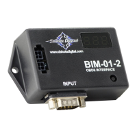
EasyManua.ls Logo

Dakota Digital BIM-01-2 User Manual

Dakota Digital BIM-01-2
12 pages
To Next Page IconTo Next Page
Page #1 background imageLoading...
Page #1 background image
[1] MAN #650500G
BIM-01-2
Bus Interface Module for OBD-II vehicle interface
This Bus Interface Module has an input to read engine information from vehicles using the J1850 GM 1996-up OBD-II
protocol, Ford 1996-up OBD-II protocol, Chrysler 2004-up OBD-II protocol, or CAN (SAE J1979) OBD-II protocol. CAN
SAE J1979 OBD-II is used on all vehicles 2008 and newer and some vehicles from 2004 2008.
There are two interface (I/O) ports on the module. Either one can be connected to the instrument system or to another
module, allowing several units to be daisy chained together.
Do not: connect the I/O port to anything other than a Dakota Digital control box or BIM.
Do not: mount the module in the engine compartment; it should be mounted in the vehicle cabin.
The BIM-01-2 normally does not use one of the 16 available bus ID’s like other Dakota Digital BIM units do. Speed and
RPM data are transmitted and updated every 0.1 second, on a dedicated bus to the display box processor. The remaining
data is sent one at a time in sequence along with the speed and RPM.
Some 2009 and newer GM engines offer boost data. If enabled, the boost data will try to default to ID Channel 9 in the
control box for the display.
The engine and transmission information that is available from the unit depends on the year, make, model, and options of
the vehicle. Some of the possible values are: engine RPM, vehicle speed, engine coolant temperature, intake air
temperature, transmission fluid temperature, transmission gear position, vacuum/boost and ambient air temperature.
A GPS-50-2 CANNOT be linked (daisy chained) to a BIM-01-2 with a BIM cable.
The two units cannot talk to the display control box at the same time.

Other manuals for Dakota Digital BIM-01-2

Questions and Answers:

Dakota Digital BIM-01-2 Specifications

General IconGeneral
Input Voltage12V DC
Product TypeBus Interface Module
CompatibilityUniversal
InputsVehicle data bus
OutputsSerial data
InstallationWiring into the vehicle's GMLAN data bus
Data ProvidedVehicle speed, RPM, fuel level, etc.
Operating Temperature85°C

Summary

Display Data Usage

Display Setup

VFD3/VFD3X Setup

Obtaining Speed from BIM-01-2

Instructions for configuring the VFD3/VFD3X to display vehicle speed from the BIM-01-2.

Obtaining RPM from BIM-01-2

Instructions for configuring the VFD3/VFD3X to display engine RPM from the BIM-01-2.

Obtaining Engine Temperature from BIM-01-2

Instructions for configuring the VFD3/VFD3X to display engine temperature from the BIM-01-2.

Obtaining Oil Pressure from BIM-01-2

Instructions for configuring VFD3/VFD3X to display oil pressure from the BIM-01-2.

VHX Setup

Obtaining Speed from BIM-01-2

Instructions for configuring the VHX to display vehicle speed from the BIM-01-2.

Obtaining RPM from BIM-01-2

Instructions for configuring the VHX to display engine RPM from the BIM-01-2.

Obtaining Engine Temperature from BIM-01-2

Instructions for configuring the VHX to display engine temperature from the BIM-01-2.

Obtaining Oil Pressure from BIM-01-2

Instructions for configuring VHX to display oil pressure from the BIM-01-2.

HDX/RTX Setup

Obtaining Speed from BIM-01-2

Instructions for configuring HDX/RTX to display vehicle speed from the BIM-01-2.

Obtaining RPM from BIM-01-2

Instructions for configuring HDX/RTX to display engine RPM from the BIM-01-2.

Obtaining Engine Temperature from BIM-01-2

Instructions for configuring HDX/RTX to display engine temp from BIM-01-2.

Obtaining Oil Pressure from BIM-01-2

Instructions for configuring HDX/RTX to display oil pressure from BIM-01-2.

BIM Setup Menu

Diagnostic Bus ID Numbers

Procedure to set or change diagnostic bus ID numbers for the BIM-01-2.

Engine Indicator Status

Enabling or disabling the engine indicator status on the BIM-01-2.

Gear Position Output

Enabling or disabling gear position output from the BIM-01-2.

Vacuum/Boost Output

Enabling or disabling vacuum/boost output from the BIM-01-2.

Ford RPM Signal

Setting RPM signal for Ford Performance control pack/Coyote Engines.

Ford Speed Signal

Setting speed signal for Ford Performance control pack/Coyote Engines.

Quick Tips

Operating Status Indicators

Interpreting the dot indicators on the BIM display for status and communication.

Data Displayed

List of available data parameters and their corresponding codes displayed by the BIM-01-2.

Troubleshooting Guide

No BIM Data / No Light

Troubleshooting steps for when the BIM unit does not power up or display data.

Scanning "J", "F", "C"

Troubleshooting steps for when the BIM display is scanning vehicle protocols.

Steady Dot Lit

Troubleshooting steps for when the BIM displays a steady dot indicating no bus activity.

Display Shows "88:8"

Troubleshooting steps for when the BIM display shows '88:8'.

Service and Repair

Technical Support

Contact information and resources for technical assistance and product support.

Return Merchandise Authorization

Procedure for returning units for repair, including packaging and required information.

Limited Lifetime Warranty

Details of Dakota Digital's limited lifetime warranty for the product.

Related product manuals