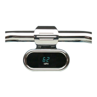
MODEL HLY-5011
BAR MOUNT
DIGITAL SPEEDOMETER
3421 W. Hovland Ave., Sioux Falls, SD 57107
Phone: (605) 332-6513 FAX: (605) 339-4106
www.dakotadigital.com
Please read this before beginning installation or wiring.
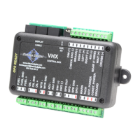
POWER
Connect the red wire from the main harness to accessory power from the ignition switch. In addition to
powering the display system.
A good quality, solid state ignition switch should be used. The contacts on a mechanical “bar” switch
can bounce due to the vibration and cause the system to momentarily loose power and reset itself.
Never connect this to a battery charger alone. It needs to have a 12 volt battery connected to it.
Battery chargers have an unregulated voltage output that will cause the system to not operate properly.
GROUND
The black wire is the main ground for display system. This should be connected directly to the negative
cable on the battery. Connecting to a tank or frame ground can cause a weak or intermittent ground connection.
A poor ground connection can cause improper or erratic operation.
SPEEDOMETER
The speed input connector plugs into the speed sensor to tell how fast you are traveling. On cable
driven applications, the external sensor connects to the speedometer cable and provides the electric signal.
The sensor has a 5/8” course thread fitting that accepts mid-80’s and earlier cables directly. For newer cycles
the speedometer cable will need to be replaced with one having the correct fitting.
With transmissions having the built-in electric sensor, a three-wire harness adapter connects the
transmission speed sensor to the speedometer. This system will also accept most after-market inductive, Hall-
effect, or ground switch sensors.
The speedometer is fully adjustable and calibration is listed below.
SPEEDOMETER CALIBRATION
The speedometer calibration is done using the function (trip) switch. The speedometer can be calibrated
two different ways. The first method is to place the unit in auto-cal mode and drive exactly one mile (one km for
metric). The second method is to place the unit in adjust mode and the speed reading can be moved up or
down while driving.
METHOD 1, AUTOCAL
1. Make sure the key is off so the gauge is not powered.
2. Press and hold the function switch.
3. Turn the key on. With the switch still held, start the bike. The display will show “ -- “.
4. Release the function switch. The display will switch between “AUtO” (auto cal) and “AdJ” (adjust).
5. When “AUtO” is displayed press the function switch. This will place the unit in auto calibration mode.
6. Release the function switch. The speedometer will show “–00.0”.
7. Drive exactly one mile (or 1km). The speedometer display will increase as signal pulses are received from
the speed sensor.
8. Press and release the function switch. The calibration value will be calculated and stored. The gauge will
now restart in normal mode with the new speed calibration.