
M
Michael GallegosAug 16, 2025
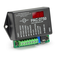
Why does my Dakota Digital Controller fan run constantly?
- Ccrystal54Aug 17, 2025
Several factors can cause the Dakota Digital Controller fan to run constantly. It could be due to an error with the controller itself, so check the display for an error message. The fan off temperature might be set too low, so increase the off temperature in the setup. A broken or shorted wire to the sender could also be the culprit, so inspect the wire for any damage and repair it. Finally, the wrong gauge might be selected, so select the appropriate gauge in the setup or perform a custom calibration if your gauge isn't supported.