Solar PV modules create current whenever light strikes them. The current created varies with the
light intensity, but even in the case of low levels of light, full voltage is given by the modules. So,
protect the solar modules from incident light during installation. Never touch uninsulated cable
ends, use only insulated tools, and make sure that the wire diameter is in accordance with the
expected currents of solar charge controller. Connections must always be made in the sequence
described below.
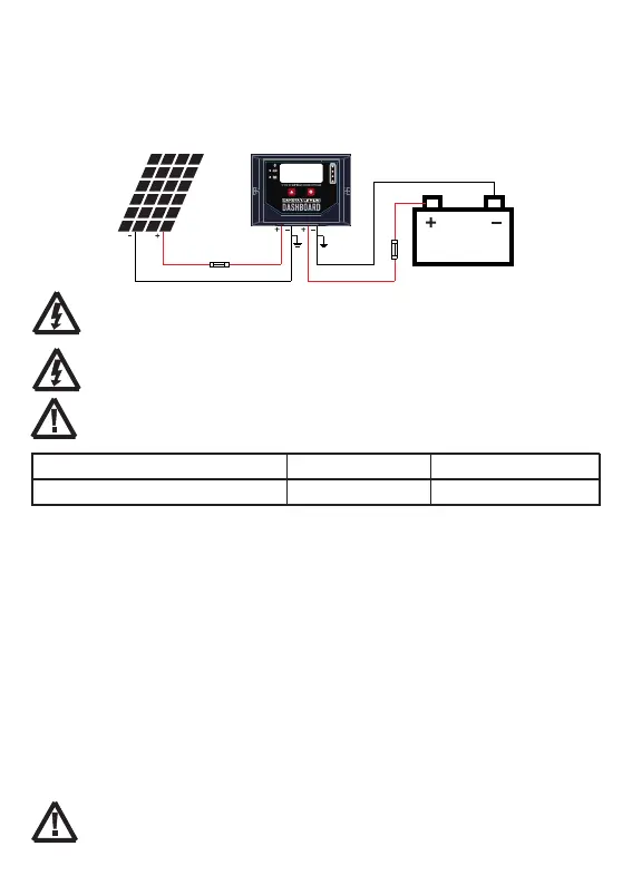
7.3 Connection
8
WARNING: Risk of electric shock! Exercise caution when handing solar wiring. The solar PV
array can produce open-circuit voltages in excess of 100V when in sunlight. Pay more
attention to it.
WARNING: Risk of explosion! Once the battery's positive and negative terminals or leads that
connect to the two terminals get short-circuited, a fire or explosion will occur. Always be
careful in operation.
1st step: Connect the battery
Connect the battery connection cable with the correct polarity to the battery terminals on the solar charge
controller (with the battery symbol). If the polarity is correct, the LCD on the controller will begin to show.
2nd step: Connect the solar module
Ensure that the solar module is protected from incident light. Ensure that the solar module does not exceed
the maximum permissible input current. Connect the solar module connection cable to the correct polarity of
the solar terminals on the solar charge controller (with the solar module symbol).
3rd step: Final work
Tighten all cables connected to the controller and remove all the debris around the controller (leaving a space
of approx. 15 cm).
CAUTION: For common-negative system, such as motorhome, it is recommended to use a
common-negative controller; but if in the common-negative system, some common-positive
equipment are used, and the positive electrode is grounded, the controller may be damaged.
Fusing is a recommendation in PV systems to provide a safety measure for connections going
from panel to controller and controller to battery. Remember to always use the recommended
wire gauge sized based on the PV system and the controller.
7.4 Grounding
Be aware that the negative terminals of controller are connected together and therefore have the same
electrical potential. If any grounding is required, always do this on the negative wires.
Cable total length one-way distance
Cable wires(AWG)
<3m
14~12AWG
3m~6m
12~10AWG
!
controller or between the controller and the battery, larger wires can be used to reduce the
voltage drop and improve performance.
The wire size is only for reference. If there is a long distance between the PV array and the
①
②
③
④