Copyright 1996-2001 ED-7244
Daktronics, Inc. Rev. 4 – 14 March 2001
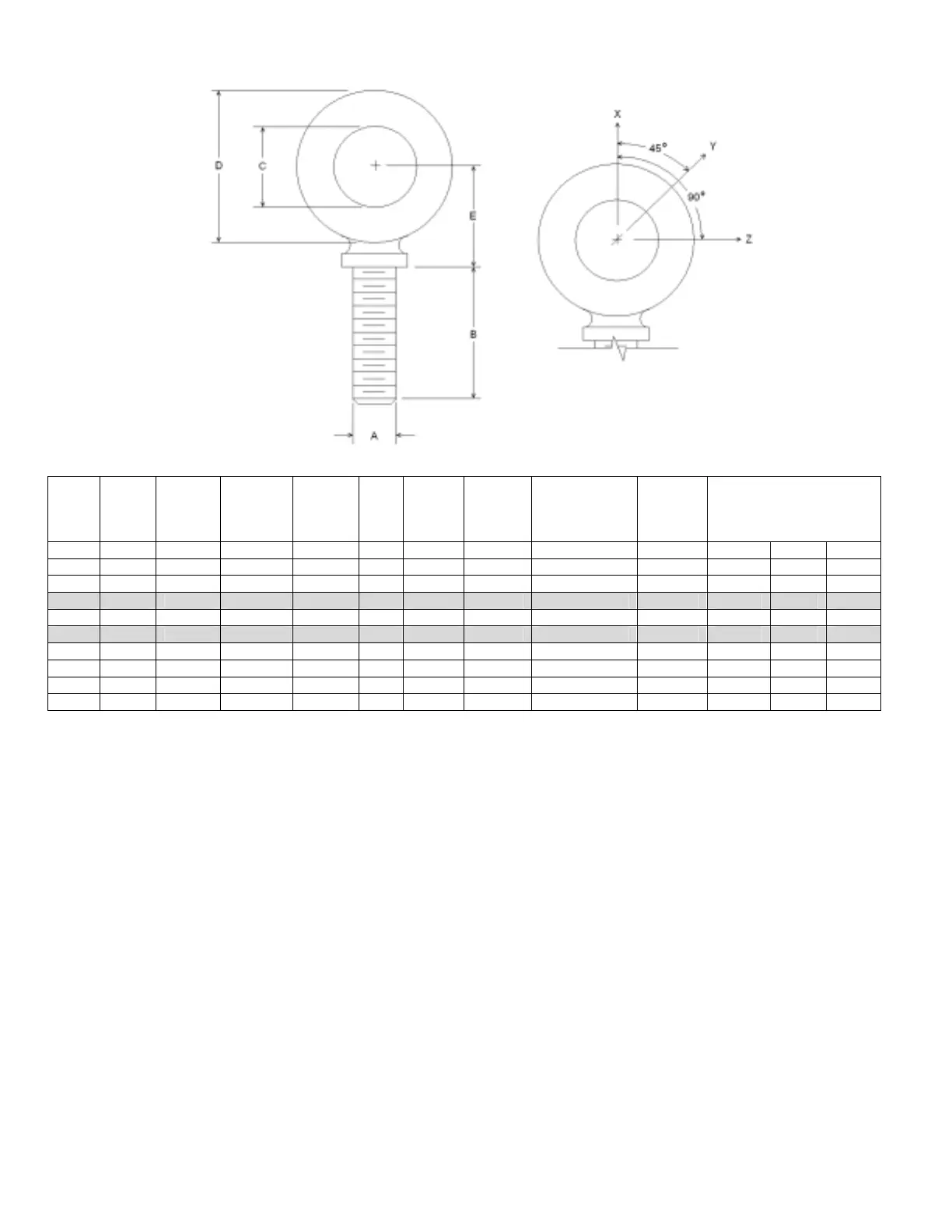
A B C D E No.
Min.
Proof
Load
(lbs.)
Min.
Break
Load
(lbs.)
Stocked
Min.
Eff.
Thrd.
Length
Line Loads
Wx Wy Wz
1/4 1 3/4 1-3/16 25/32 21 600 2,000 Blank 1/4-20 7/8 400 100 80
3/8 1-1/4 1 1-21/32 1-3/16 23 2,100 5,000 Blank 3/8-16 1-1/8 1,400 350 250
1/2 1-1/2 1-3/16 2-1/16 1-13/32 25 3,900 9,200 Blank 1/2-13 1-11/32 2,600 650 520
9/16 1-5/8 1-9/32 2-13/16 1-17/32 26 4,500 11,830 Blank 9/16-12 1-3/8 3,000 750 600
5/8 1-3/4 1-3/8 2-1/2 1-11/16 27 6,000 14,700 Blank 5/8-11 1-9/16 4,000 1,000 800
3/4 2 1-1/2 2-13/16 1-13/16 28 9,000 21,700 Blank 3/4-10 1-5/8 6,000 1,500 1,200
7/8 2-1/4 1-11/16 3-1/4 2-1/16 29 10,000 30,000 Blank 7/8-9 1-13/16 6,600 1,670 1,330
1 2-1/2 1-13/16 3-9/16 2-5/16 30 12,000 39,400 Blank 1-8 2-1/16 8,000 2,000 1,600
1-1/2 3-1/2 2-9/16 5-1/2 3-5/32 34 27,000 91,300 Blank 1-1/2-6 3 17,800 4,500 3,600
A. Do not use eyebolts on angular lifts unless absolutely necessary. For angular lifts, the shoulder pattern
eyebolt is preferred.
B. Load should always be applied to eyebolts in the plane of the eye, not at some angle to this plane.
C. Shoulder eyebolts must be properly seated (should bear firmly against the mating part), otherwise the
working loads must be reduced to those indicated for regular eyebolts. A washer or spacer may be
required to put the plane of the eye in the direction of the load when the shoulder is seated.
D. No load greater than the safe working load listed in the data table should be used.
E. To obtain the greatest strength from the eyebolt, it must fit reasonably tight in its mounting hole to prevent
accidental unscrewing due to twist of cable.
F. Eyebolts should never be painted or otherwise coated when used for lifting. Such coatings may cover
potential flaws in the eyebolt.
G. To attain the safe working loads listed for regular eyebolts, 90% of the thread length must be engaged.
 Loading...

