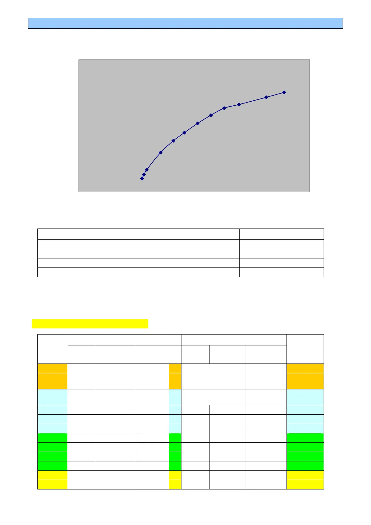
23 POLAR DIAGRAM
POLAR DIAGRAM
DRAG
DOWNFORCE
REAR (upper wing) FRONT (flap)
LDF = Low Down Force (single small) no flap
MDF = Medium Down Force (twin small) MF = Medium Flap
HDF = High Down Force (small and mid combined) SF = Standard Flap
UHDF = Ultra High Down Force (twin mid) idem
• All configurations give 38% of total downforce to the front.
• Front ride height is 10mm and rear ride height is 24mm, which corresponds to
typical medium speed dynamic ride heights.
WING SETTING CONFIGURATIONS
REAR
FRONT
CFG
TOP
TYPE
TOP
SETTING
LOWER
FLAP
TYPE
FLAP
SETTING
MAIN
PLANE
CFG
1 LDF 2 3 NONE -1 1
2 LDF 8 3
NONE
-1 +Gurney
110 x 10mm
2
3 MDF 2 -1 NONE
-1
+Gurney
200 x 10mm
3
4 MDF 12 3 MF 10 -1 4
5 MDF 17 3 MF 14 -1 5
6 MDF 23 3 MF 19 -1 6
7 HDF 12 7 SF 13 -1 7
8 HDF 17 7 SF 16 -1 8
9 HDF 20 11 SF 19 -1 9
10 HDF 23 15 SF 21 -1 10
11 UHDF 7 SF 28 -1 11
12 UHDF 15 SF 31 -1 12
4
6
8
12