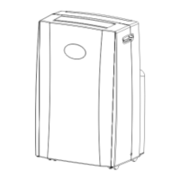
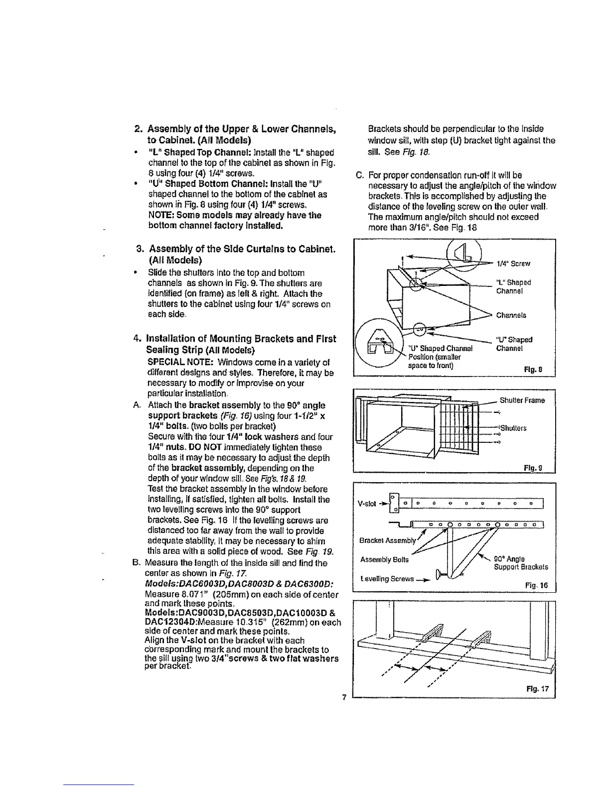
2. Assembly of 1he Upper & Lower Channels,
to CabineL (All Models)
• "L" ShapedTop Channel:Install the "L" shaped
channelto the top oFthecabinetas showninFig,
8 using four (4) 1/4"screws.
• "U;' Shaped Bottom Channel:Installthe "U"
shapedchannelto thebottomof thecabinelas
shownthFig.8 usingfour(4) 1/4"screws_
NOTE.Some models may alreadyhavethe
bottom channelfactory Installed,
3. Assembly of the Side Curtains to Cabinet.
(All Models)
, Slidethe shutters into thetopand boltom
channelsas shown inFig,9.The shulters are
idsnlified (on frame)as left & right Attach the
shuttersto thecabinetusingfour 1/4"screws on
eachside.
4. Installation of Mounting Brackets and First
Sealing Strip (All Models)
SPECIAL NOTE; Windows come in a variety of
different designs and styles_ Therefore, it may be
necessary to modify or Improvise on your
particular installation.
A. Attach the bracket assembly to the 90° angle
support brackets (Fig., 16) using four 1-H2" x
114" bolts. (two bolts per bracket)
Secure with the four 114" lock washers and four
1t4" nuts. DO NOT immediately tighten these
bolts as it may be necessary to adjust the depth
of the bracket assembly, depending on the
depth of your window sill SeeFig's.18& I9o
Tea! the bracket assembly In the window before
Installing, if satisfied, tighten all bolts. Install the
two levelling screws tnto the 90° support
brackets.See Fig. 16 If the levetling screwsare
distanced too far away from the wall to provide
adequate stability, it may be necessary to shim
this area with a solid piece of wood. See Fig 19,
B° Measure the length o1the inside sill and lind the
center as shown in Fig. t"7.
ModeIs:DAC6OO3D, DACeOO3D & DAC6300D:
Measure 8.071" (205ram) on each side of center
and mark these points.
Models:DAC9003D,DAC8503D,DAC |0003D &
DAC12304D:Measure 10.315" (262mm) on each
side of center and mark these poinlSo
Align the V-slot on the brackel with each
cbrrespending mark and mount the brackets to
the silt uping two 314"screws & two flat washers
per oracKet
Brackets should be pe_'pendicular to the inside
window sill, wiIh step (U) bracket tight against the
sill. See Fig. 18.
C. For proper condansatlon rumolf It will be
necessary to adjust the angle/pitch of the window
brackets. This is accomplished by adjus!ing the
distance of the leveling screw on the outer wall.
The maximum angle/pitch should not exceed
more than 3116". See Fig. 18
I/4"Screw
"L" Shaped
Channel
Channels
"Lr' Shaped
Channel
Fig. S
Shutters
Fig,9
V-alol"_--_ o o o = o o o o ]
t availing Screws _ _ Support Btackels
Fig.16