Do you have a question about the d&b audiotechnik J Series and is the answer not in the manual?
Defines the authorized applications and purpose for the J-Series rigging components.
Details the weight limitations and essential safety parameters for the Z5300 J Flying frame and array setups.
Provides critical guidelines for safe practices during assembly, setup, and general operation of the rigging system.
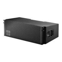
Introduces the Z5300 J Flying frame, outlining its design and primary role in suspending J-Series loudspeakers.
Lists and describes all components included with or integral to the Z5300 J Flying frame.
Details the central bar of the Z5300 J Flying frame, including its hole grid and user instructions.
Provides the mechanical dimensions of the Z5300 J Flying frame in millimeters and inches.
Specifies the dimensions of the mounting plate compatible with the Z5300 J Flying frame.
Describes the Z5303 J Safety chain, its specifications, and use as a secondary safety device.
Introduces additional components available for use with the J-Series rigging system.
Details the Z5305 J Hoist connector chain for attaching lifting motors to the J Flying frame.
Describes the E7441 Touring case designed for storing and transporting a Z5300 J Flying frame and accessories.
Covers essential preliminary steps before commencing rigging setup, including planning and area clearance.
Highlights the importance of inspecting all system components for faults before use.
Explains the function and assembly procedure for the J-Series Locking pins used in the rigging system.
Details how to adjust the Splay link position on the Z5300 J Flying frame based on cabinet type (J8/J12 or J-SUB).
Guides the process of suspending the Z5300 J Flying frame using load adapters and hoists.
Describes the J Load adapter, its attachment to the frame, and safety checks before lifting.
Explains the procedure and limits for suspending an array using a single hoist point.
Details the procedure and limits for suspending an array using two hoist points.
Emphasizes the requirement for independent secondary safety suspension to prevent drops.
Details the attachment points and recommended safety chain for secondary safety on the Z5300 J Flying frame.
Covers setting the horizontal aiming of the array and securing it against rotation and swing, especially in open air.
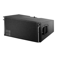
Describes the assembly process for a standard J8/J12 loudspeaker array configuration.
Details the preparatory steps and sequence for assembling a J8/J12 array on the ground.
Provides instructions for safely dismantling a J8/J12 array, following similar safety protocols as assembly.
Explains the assembly of mixed arrays featuring J-SUB and J8/J12 cabinets, often requiring two flying frames.
Covers preparations and step-by-step assembly for mixed J-SUB and J8/J12 arrays, starting with the first J-SUB.
Outlines the procedure for dismantling mixed J-SUB and J8/J12 arrays in reverse order of assembly.
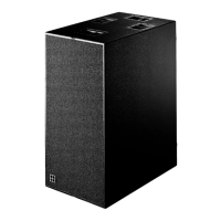
Describes the setup for arrays consisting solely of J-SUB cabinets, including optional curvature.
Details configurations for ground-stacked J-Series arrays, emphasizing security against movement and tipping.
Specifies the maximum number of cabinets allowed for J-Series ground stack configurations.
Covers the necessary preparations for ground stack setups, including Splay link positioning.
Provides a step-by-step guide for assembling J8/J12 cabinets in a ground stack configuration with a flying frame.
Explains how to assemble ground stacks combining J-SUB and J8/J12 cabinets, with the flying frame at the top.
Describes the setup for conventional ground stacks of J-SUB cabinets, including interconnection methods.
Provides instructions for the proper transport and storage of J-Series rigging components to prevent damage.
Outlines procedures for regular visual and functional checks of cabinets, locking pins, and frame components.
Guides the environmentally compliant disposal of J-Series rigging components when they are no longer in use.
| Brand | d&b audiotechnik |
|---|---|
| Model | J Series |
| Category | Speakers |
| Language | English |