Do you have a question about the d&b audiotechnik GSL8 and is the answer not in the manual?
Details on safe loudspeaker usage, potential hearing damage, and deployment guidelines.
Information on the d&b ArrayCalc simulation software for line array design.
Specifies the intended use of d&b SL-Series loudspeakers and applicable amplifiers.
Details on the NLT4 F connector wiring and d&b LoadMatch function.
Information on amplifier output modes, line and arc setups, and AP setup.
Explains CUT, CPL, and HFC functions for acoustic adjustment.
Graphs showing horizontal dispersion angle over frequency for GSL8 and GSL12.
Provides system and loudspeaker data including frequency response and impedance.
Declaration of conformity for GSL8 and GSL12 loudspeakers with EC directives.
Guidance on the disposal of electrical and electronic equipment.
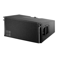
The d&b GSL8/GSL12 loudspeaker is a high-performance line array system designed for large-scale sound reinforcement applications, offering robust functionality and precise acoustic control. These loudspeakers are engineered to deliver exceptional sound quality and consistent dispersion, making them suitable for demanding professional audio environments.
The GSL8 and GSL12 are 3-way line array loudspeakers, acoustically and mechanically compatible, designed to be deployed in vertical columns. The GSL8 provides an 80° constant directivity dispersion pattern in the horizontal plane, while the GSL12 offers a wider 120° horizontal dispersion. Both models feature a symmetrical arrangement of components around the cabinet's center axis, ensuring a perfectly symmetrical dispersion pattern and a smooth crossover design with a well-defined overlap of adjacent frequency bands. This design maintains directivity across the entire frequency range, extending from 45 Hz to above 18 kHz.
Each cabinet houses a sophisticated driver configuration: two 14" neodymium forward LF drivers, two 10" neodymium side-firing LF drivers, one high-sensitivity horn-loaded 10" MF driver, and three 1.4" exit HF compression drivers with 3.4" coils mounted to a dedicated wave shaping device. This precise arrangement allows the cylindrical wave segments of each cabinet to couple without gaps, summing coherently to produce a powerful and articulate sound field.
GSL cabinets are driven by two channels of an applicable d&b amplifier, which provides dedicated processing functions for the front LF and passively crossed-over side-firing LF and MF/HF sections. This active-passive crossover scheme optimizes performance and efficiency.
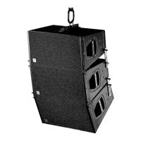
The GSL8/GSL12 system is designed for flexible deployment, primarily in flown line array configurations. When used with the GSL Flying frame, up to 24 GSL8 cabinets can be flown in a single vertical column. Splay angles between adjacent cabinets can be precisely set in 1° increments, ranging from 0° to 7°, allowing for fine-tuning of the array's curvature and coverage.
The system integrates seamlessly with d&b ArrayCalc simulation software, which is essential for designing line arrays for both safety and acoustic reasons. ArrayCalc provides typical array configurations within permitted load limits and helps users understand mechanical load conditions and limitations. Detailed information on using ArrayCalc is available through its Help system and dedicated technical information documents (TI 385).
Operation of the GSL8/GSL12 loudspeakers involves specific amplifier output modes: "2-Way Active." The system offers "Line" and "Arc" setups, which can be combined within a single array. The "Line" setup is intended for long-throw array sections with minimal splay angles (0° or 1°), considering cabinet interaction effects between straight and curved sections. The "Arc" setup is designed for use in curved array sections.
A key feature is the integration with d&b ArrayProcessing (AP). The "AP setup" contains data generated by ArrayCalc and transferred to the amplifiers via the d&b Remote network (OCA/AES70) using R1. Once this data is sent, the AP setup is automatically activated, providing the system with its target response and accounting for coupling effects caused by array length and shape.
Acoustic adjustment functions include CUT, CPL (Coupling), and HFC (High Frequency Compensation). The CUT mode reduces the low-frequency level, configuring the array for use with actively driven d&b SL-SUB or SL-GSUB cabinets. The CPL function compensates for coupling effects between cabinets by reducing low and low-mid frequency levels, offering a two-stage filter (Low/Mid) for independent shaping of responses. CPL values can be adjusted from +5 to -5 (Low) and 0 to -8 (Mid) in 0.5 increments. It is crucial that all cabinets within an array operate with the same CPL setting. The HFC function, available for Line/Arc setups, compensates for high-frequency energy loss due to air absorption over long distances, with settings for 40 m (HFC1) and 80 m (HFC2) of additional distance from a reference position. This ensures correct sound balance between close and remote audience areas.
The cabinet enclosures are constructed from marine plywood, providing durability and resistance to environmental factors. They feature an impact and weather-protected PCP (Polyurea Cabinet Protection) finish, ensuring longevity in demanding touring and installation environments. The front and side panels incorporate a rigid metal grill backed by acoustically transparent and water-repellent fabric, protecting the internal components while maintaining acoustic integrity.
For ease of handling and transport, each side panel incorporates a handle, with two additional handles provided at the rear of the cabinet.
The rigging components are robust and integrated into the cabinet design. Cabinets are mechanically connected using rigging strands on both sides of the cabinet front and a central strand at the rear. All necessary rigging components are mounted on the cabinet and can be folded out or slid out when needed. A detailed description of the SL-Series rigging components is provided in the SL-Series Rigging manual.
Regular checks are recommended for both the loudspeaker housings and accessories to identify any visible signs of wear and tear, and replacements should be made as necessary. All load-bearing bolts in the mounting devices should also be regularly checked to ensure safety and structural integrity.
The d&b website is a valuable resource for obtaining the latest version of the product manual and other relevant documents. When reselling the product, it is important to hand over this document to the new owner to ensure they have access to critical information regarding its safe and proper use.
| Type | Line array module |
|---|---|
| Configuration | 3-way |
| HF drivers | 2 x 1.4" |
| Max SPL | 145 dB |
| Nominal Impedance | 8 Ω |
| Enclosure Material | Plywood |
| Grille | Steel grille with foam |
| Frequency Range | 45 Hz - 18 kHz (-5 dB) |