Do you have a question about the Danelec Marine DM100 VDR and is the answer not in the manual?
Lists related documents and manuals.
Glossary of terms and acronyms used.
Defines generic and specific product terms.
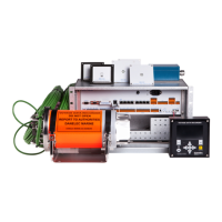
Details the DAU, its function and location.
Describes the BCP's role as user interface and for self-tests.
Explains the placement and types of BMUs.
Location and description of the fixed data capsule.
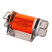
Details the float-free capsule requirements and installation.
Explains the RVI's function, optionality, and connection.
Describes the SIU's function, types, and connection.
The primary user interface for the VDR.
Displays system errors and cautions on the BCP.
Procedure for the VDR's self-test.
How to reset display brightness to default settings.
Steps for downloading VDR data to a USB stick.
Explains the meaning of the DPU's power LEDs.
Describes the function and operation of the AC breaker.
Details the ship's AC power input for the VDR.
Explains the function of the battery switch on the DPU.
Explains the tri-color VDR status LED meanings.
Describes the Main CPU LED status indicators.
Explains the LEDs on the Ethernet connectors.
Describes the LEDs on the Uni-rack.
Indicates the presence of AC power.
Describes the AC breaker for the Uni-rack.
Explains the Ethernet link and activity LEDs.
Specifies the required UR address settings.
Describes the LEDs on the Module Rack.
Indicates the presence of AC power.
Indicates module detection in the rack.
Describes the AC breaker for the Module Rack.
Explains Ethernet connector LEDs on the Module Rack.
Maps card numbers to interface numbers for digital interfaces.
Specifies the MR address settings for the SIU.
Lists and explains various error codes displayed by the BCP.
Verifying VDR functionality after service.
Lists common spare parts for the VDR system.
| Category | Voyage Data Recorder (VDR) |
|---|---|
| Manufacturer | Danelec Marine |
| Recording Duration | 48 hours |
| Power Supply | 24 VDC |
| Operating Temperature | -15°C to +55°C |
| Standard Compliance | IMO MSC.333(90), IEC 61996-1 Ed.2 |
| Data Recorded | AIS, ECDIS, Radar |
| Audio Channels | 4 |
| Data Interfaces | Ethernet, Serial |
| Data Capsule | Float-free |
| Dimensions | 400 x 300 x 200 mm |
| Weight | Approximately 15 kg |