Do you have a question about the Danfoss air and is the answer not in the manual?
Guidance on checking shipment completeness and following installation instructions in sequence for best results.
Diagram and explanation of the proper method for installing the siphon for condensate drainage.
Illustration of improper siphon installation that risks condensate drain failure and water leakage.
Important note that the siphon is a separate accessory and requires checking for correct adjustment.
Top view diagram for attic units showing power supply, CCM module, and air intake/exhaust connections.
Mandatory requirement to maintain 60 cm free space in front of the unit to ensure adequate service access.
Close-up view of wall bracket detail, illustrating the placement of rubber separators for vibration damping.
Diagram showing the top view of a wall unit, indicating the location of the condensate connection.
Guidance on maintaining 60 cm free space in front of wall units to facilitate service access.
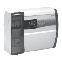
Step-by-step guide for securely mounting the Communication Control Module (CCM) onto its wall bracket.
Instructions for safely and correctly removing the CCM module from its wall bracket.
Important note regarding accessory connections and the need to remove specific pins on the ventilation system plug.
Guidance on resolving issues with wireless connections, including signal strength and interference.
Recommendations for placing the Air Dial for accurate temperature sensing and optimal wireless communication.
Steps to perform a link test to verify wireless signal strength before permanently mounting the Air Dial.
Explanation of why balancing air volumes is crucial for system efficiency and preventing house issues like fungus.
Instructions for system operation and balancing when outdoor temperatures are below -3°C.
Procedure for balancing air volumes when using Danfoss-supplied duct systems, referencing pre-set values.
Steps to access the hidden service menu for setting basic fan speeds and commissioning the system.
Procedure for balancing air volumes when using duct systems not supplied by Danfoss, following project manager instructions.
Diagram showing the top view of the w1 unit with dimensions and port layout.
Diagram showing the front view of the w1 unit with dimensions and weight indication.
Isometric drawing of the w1 unit with the front panel removed, highlighting internal components.
Diagram showing the top view of the w2 unit with dimensions and port layout.
Diagram showing the front view of the w2 unit with dimensions and weight indication.
Isometric drawing of the w2 unit with the front panel removed, highlighting internal components.
Diagram showing the right view of the a2 unit with dimensions and port layout.
Diagram showing the front view of the a2 unit with dimensions and weight indication.
Diagram showing the front view of the a3 unit with dimensions and weight indication.
Diagram illustrating internal components and connection points after removing the unit's front panel.
Graph illustrating flow rate versus external pressure for the w1 unit.
Table detailing typical operating points, flow, pressure, SFP, and power consumption for the w1 unit.
Graph showing dry efficiency and condensation efficiency ratings for the w1 unit.
Graph illustrating flow rate versus external pressure for the w2 unit.
Table detailing typical operating points, flow, pressure, SFP, and power consumption for the w2 unit.
Graph showing dry efficiency and condensation efficiency ratings for the w2 unit.
Graph illustrating flow rate versus external pressure for the a2 unit.
Table detailing typical operating points, flow, pressure, SFP, and power consumption for the a2 unit.
Graph showing dry efficiency and condensation efficiency ratings for the a2 unit.
Graph illustrating flow rate versus external pressure for the a3 unit.
Table detailing typical operating points, flow, pressure, SFP, and power consumption for the a3 unit.
Graph showing dry efficiency and condensation efficiency ratings for the a3 unit.
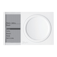
Description of how to activate the service menu via the Air Dial button for installer-specific settings.
Explanation of the 'Back' function for navigating out of service menu options.
Accessing system information, including fan steps displayed without rounding.
Function to set or manage the filter replacement reminder timer within the service menu.
Option to select the desired display language for the Air Dial interface.
Installer control mode (0-100%) for setting basic fan speeds and system operation parameters.
Procedure to test the wireless connection strength between the Air Dial and the CCM module.
Crucial step to record current fan steps from 'Service > Info > basic steps' before resetting.
Steps to reset the Air Dial by removing and reinserting batteries while holding the button.
Procedure to reset the CCM module by reconnecting its cable while pressing its button.
Confirmation that the system is reset and ready for re-registration as per chapter 3 instructions.
General advice on valve placement, considering usage areas, house features, and potential obstructions.
Tips for positioning air diffusion valves to avoid direct airflow over seating or sleeping areas.
Recommendations for placing extraction valves near moisture or contamination sources like bathrooms.
Important reminder to avoid damaging the ceiling's damp course during drilling and to repair it afterwards.
Instructions for securely fixing the bayonet socket to the ceiling, with tips for gypsum ceilings.
Guidance on adapting ducts and using necessary fittings when passing through insulation layers.
Illustrations showing examples of proper duct installation, including suspension and clipping methods.
Important notes on duct placement, insulation, vibration damping, and avoiding damaged components.
Safety advice regarding the use of appropriate protective equipment when adapting duct sections.
Instructions for inserting and fixing duct connectors using self-tapping screws or pop rivets.
Recommendations for routing crossing ducts to minimize heat loss and reduce pressure drop.
Guidance on using T-sections and RCFU reductions for modifying duct branches and main ducts.
Instructions for making flexible connections between ducts and the unit to prevent vibration transfer.
Important notes on minimum insulation thickness for supply, extract, fresh air intake, and sound dampers.
Illustration and recommendation for insulation option A, using layered lamella mat with staggered joints.
Illustration showing insulation option B for duct systems.
Illustration demonstrating common mistakes in duct insulation that can reduce effectiveness.
Disclaimer that insulation values are recommendations and country-specific regulations must be followed.
Diagram illustrating a system with a single silencer placed after the unit for overall sound damping.
Diagram showing a system with two silencers used for branching to multiple rooms.
Recommendation for using specific silencers to reduce noise transmission between individual rooms.
Recommendations for installing roof terminals on tiled roofs using specific insulated duct components.
Important guidance on positioning discharge terminals relative to windows for optimal airflow and aesthetics.
Instructions for adjusting supply air valves, including initial closing and specified opening turns.
Instructions for adjusting extract air valves, including setting position 0 and rotating the cone.
Statement clarifying that the provided valve adjustment settings are guidelines and may vary.
Information on contacting Danfoss Ventilation A/S to find an approved installer for system setup.
| Brand | Danfoss |
|---|---|
| Model | air |
| Category | Air Conditioner |
| Language | English |