b) Modem
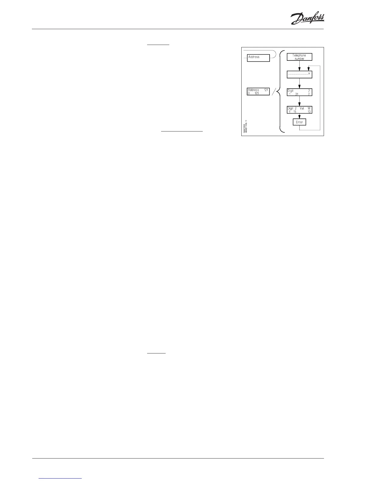
Display and setting of the “Address”
fi eld for a selected line in the router table.
Selection of port number =
1: Address number of the unit the
datagram is to be sent to in the net-
work is indicated here
2: The telephone number the
modem is to call is indicated
here.
“Telephone number”
Acess display
“______________x”
The actual telephone number for the selected line in the router table.
The telephone number may consist of up to max. 30 signifi cant digits
compo sed of fi gures and modem codes. All telephone numbers must be
terminated with ‘x’ (see below).
“Digit”
Selection of digit to be keyed/changed. Only one digit is selected.
“Digit xx Value.”
Digits/codes that can be keyed:
The fi gures 0... 9 are digits of the telephone number.
Figures above 10 are modem codes.
For a description of the codes, see the modem manual.
0... 9
10 = x: End of telephone number
11 = P: Pulse signalling
12 = T: Tone signalling
13 = W: Wait for new dial tone
14 = ,: Pause for 2 seconds
15 = %n: Modifi es baud rate
16 = *: Special character for private switching system
17 = #: Special character for private switching system
Example:
0W 12 34 56 WP 78 9x
where the digits have the following signifi cance:
0 “get a public line”
W “wait for new dial tone”
1 - 6 “phone number 123456”
W “wait for new dial tone”
P “choose pulse signalling”
7 - 9 “through-call to extension 789”
x “end of telephone number”
c) TCP/IP
Setting performed as for modem. Just set an IP address instead of a telephone
number.
30 Manual RS8DT102 © Danfoss 09/2004 AKA 245