Danfoss – 17VUBMA102
2.10 Installation principle, DHP-A
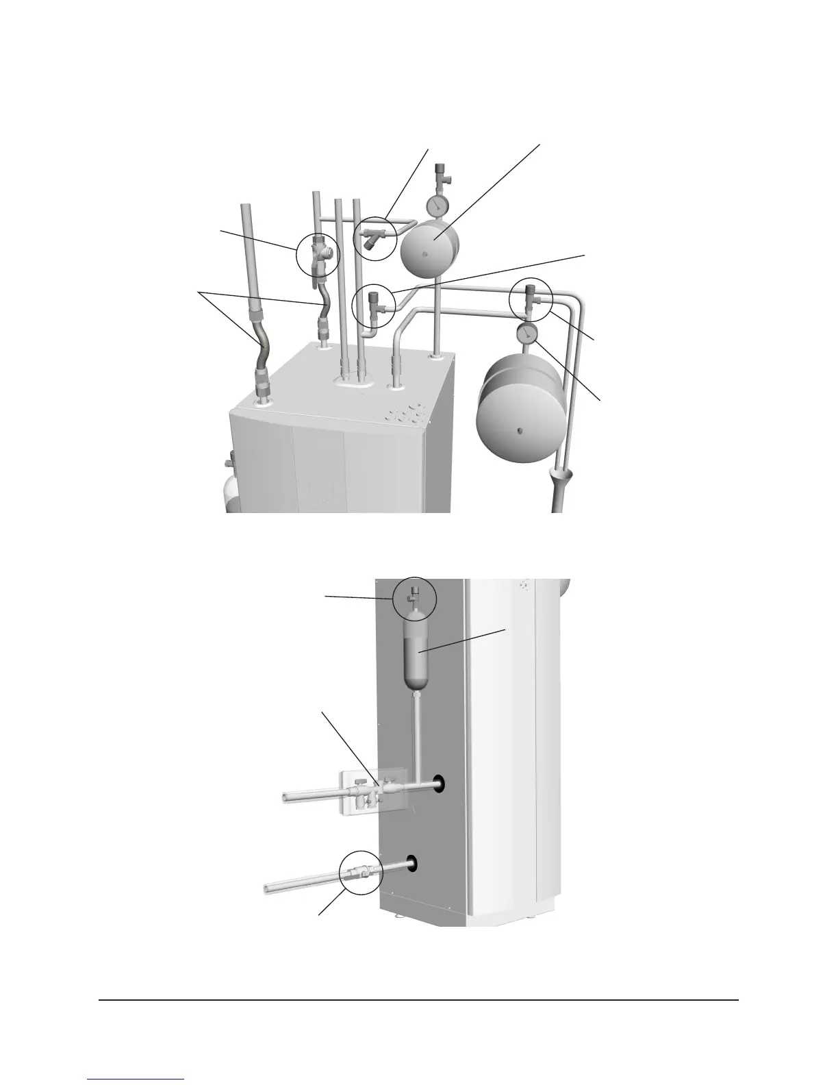
The image shows the principles of a piping installation with all components.
Figure 13: Principle solution for a piping installation.
Figure 14: Principle solution for a brine installation.
Safety valve, 1.5 bar
Location of the bleed and expan-
sion tank when the outdoor unit
is located at the same level or
lower than the heat pump.
NOTE! The fluid level in the tank
must be above the highest point
of the outdoor unit.
Filling kit incl.
strainer
Shut-off valve
Strainer
Brine in
Brine out
Location of expansion tank, pressure
gauge, and safety valve (1.5 bar) at
pressurised brine circuit when the
outdoor unit is positioned higher
than the heat pump.
Safety valve,
Pressure gauge
Filler tap
HW = Hot water
CW = Cold water
Exp = Expansion
Exp BRINE = Expansion
brine circuit
HW
Expansion
tank
To
outlet
Supply pipe
Return pipe
Safety valve, 9 bar
cold water
CW
Exp
Shut-off valve and
strainer
Exp BRINE
Flexible hoses