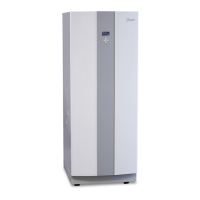
Figure 9. Components
Symbol explanation
1 Heating system supply pipe 10 Drying filter
2 Brine out to outdoor unit 11 Expansion valve
3 Return pipe, heating system 12 Shunt valve defrosting
4 Auxiliary heating, immersion heater 13 Brine in to defrosting tank during defrosting
5 Electrical panel 14 Condenser
6 Heating system circulation pump 15 Compressor
7 Evaporator 16 Low pressure switch
8 Circulation pump coolant system 17 Operating pressure switches
9 Exchange valve, heating system 18 High pressure switch
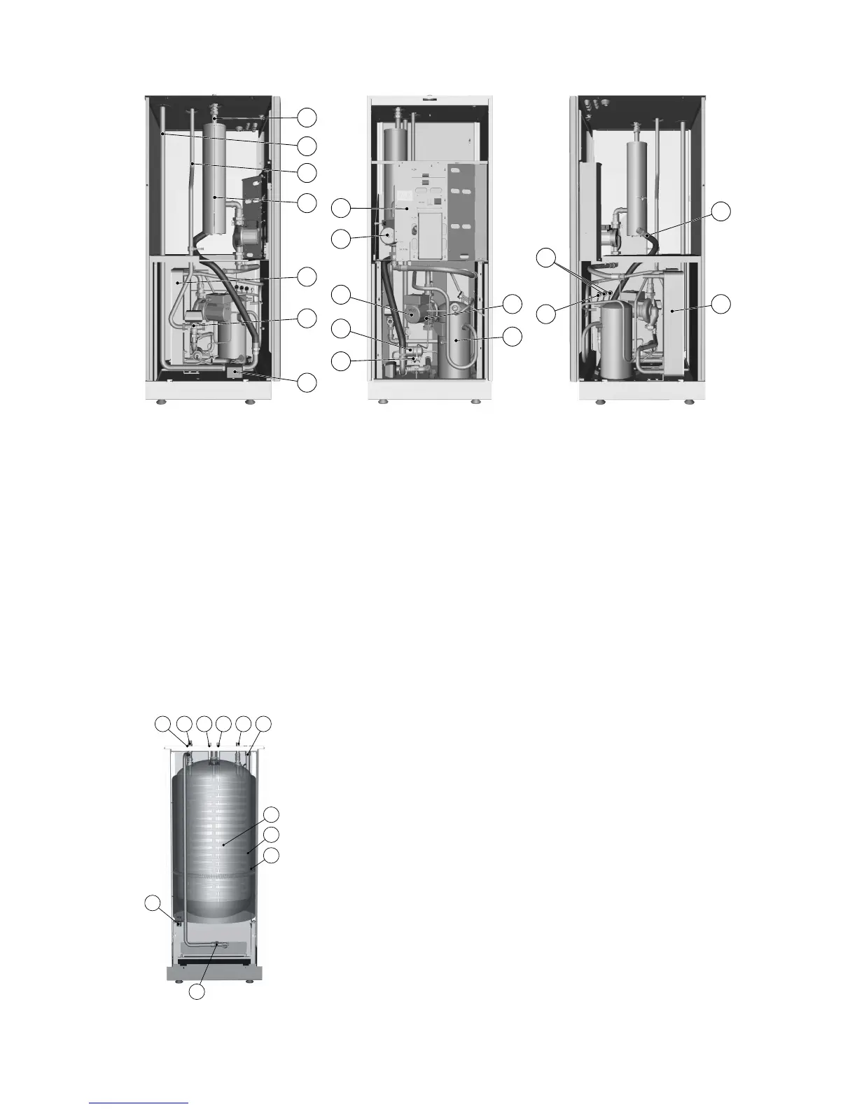
Symbol explanation
1 Defrosting tank
2 Water heater
3 TWS coil
4 Connection, expansion line when outdoor unit is positioned at
high level
5 Connection, to TWS coil
6 Cold water line, 22 mm
7 Hot water line, 22 mm
8 Bleed valve, at stainless steel water heater
9 Connection, brine out, during defrost
10 Connection, brine from heat pump
11 Connection, return pipe to heat pump
16 – Service instructions VMGFC302
 Loading...