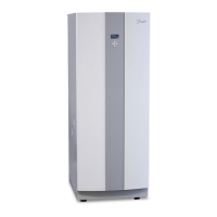
2.5 DHP-A, DHP-A Opti
Dimensions and connections
The brine pipes can be connected on either the left or right-hand
sides of the heat pump.
DHP-A, DHP-A Opti, Dimensions and connections.Figure 12:
Position Name
1 Brine in, 28 Cu
2 Brine out, 28 Cu
3 Lead-in for incoming power supply, sensors and communication
cable
4 Heating system supply line, 22 Cu: 6-10 kW, 28 Cu: 12 kW
5 Heating system return line, 22 Cu: 6-10 kW, 28 Cu: 12 kW
6 Expansion pipe, 22 Cu
7 Hot water pipe, 22 Brass
8 Cold water pipe, 22 Brass
9 Expansion outlet brine circuit, DN25 int.
10 Safety valve for temperature and pressure (mounted only on cer-
tain models, see chapter 6)
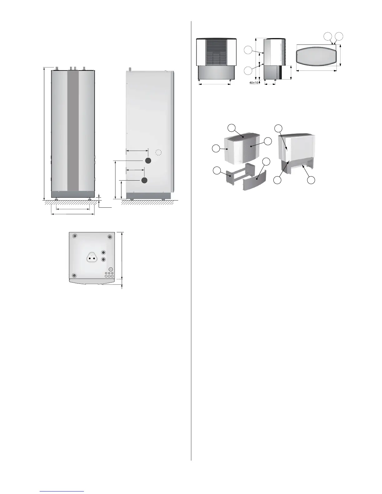
Outdoor unit, Dimensions and connections. Figure 13:
Position Name
1 Brine in (from HP Brine out) 28 Cu
2 Brine out (to HP Brine in) 28 Cu
Outdoor unit components and connectionsFigure 14:
Position Name
1 Outdoor unit
2 Cover
3 Front cover
4 Stand
5 Cover
6 Connection, brine in
7 Connection, brine out
8 Connection, drain drip tray
Check that the delivery of the outdoor unit contains the following:
• Outdoorunit
• Disassembledstand
• Necessaryscrews,nutsandwashers.
• Defrostersensor
 Loading...