EKC 331T Instructions RI8GZ353 © Danfoss 05/2006 5
ENGLISH
Operation
Menu survey
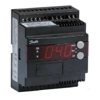
Light-emitting diodes (LED) on front panel
There are four LED’s on the front panel which will light up
when the relays are operated.
All LED’s will ash if there is an error in the regulation. In this
situation you can upload the error code on the display and
cancel the alarm by pushing the top button briey.
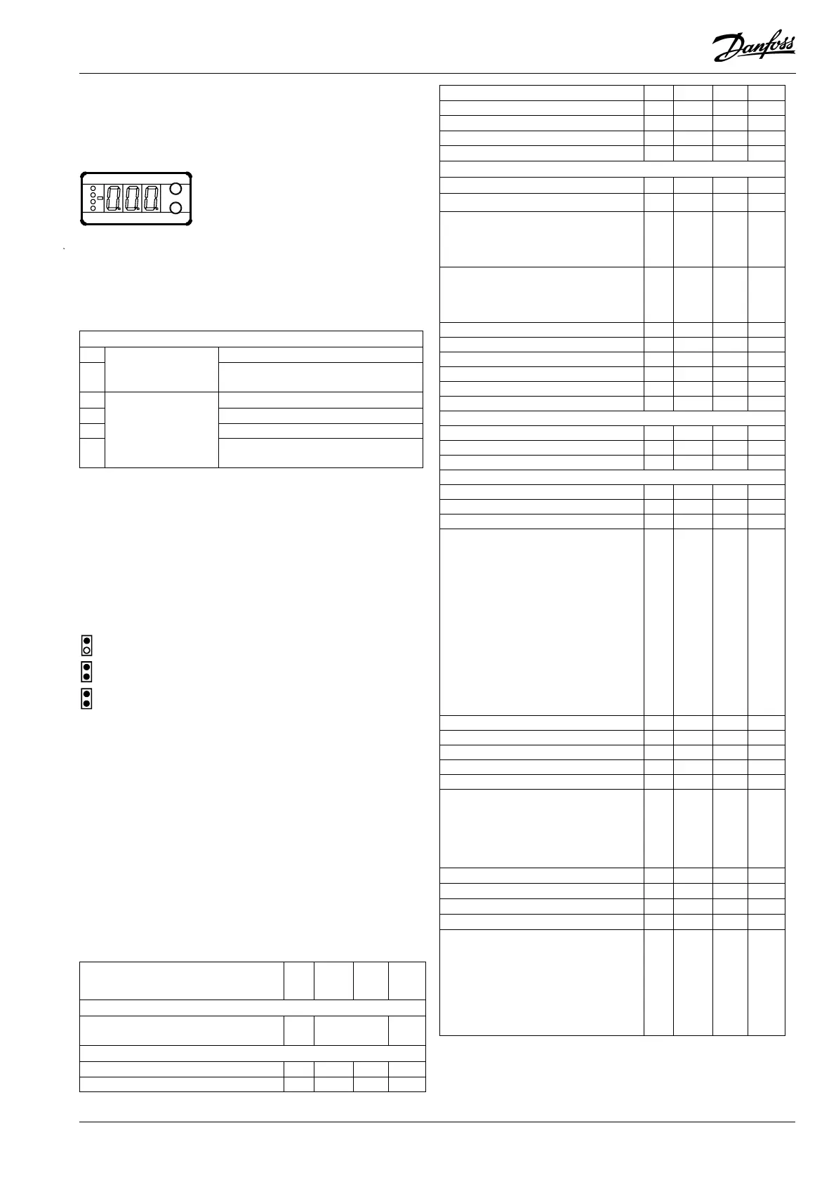
Display
The values will be shown with three digits, and with a setting
you can determine whether the temperature are to be shown
in °C or in °F.
The buttons
When you want to change a setting, the two buttons will give
you a higher or lower value depending on the button you are
pushing. But before you change the value, you must have
access to the menu. You obtain this by pushing the upper
button for a couple of seconds - you will then enter the column
with parameter codes. Find the parameter code you want to
change and push the two buttons simultaneously. When you have
changed the value, save the new value by once more pushing the
two buttons simultaneously.
Gives access to the menu
(or cutout an alarm)
Gives access to changes
Saves a change
Examples of operations
Set the regulation’s set point
1. Push the two buttons simultaneously
2. Push one of the buttons and select the new value
3. Push both buttons again to conclude the setting
Set one of the other menus
1. Push the upper button until a parameter is shown
2. Push one of the buttons and nd the parameter you want
to change
3. Push both buttons simultaneously until the parameter value
is shown
4. Push one of the buttons and select the new value
5. Push both buttons again to conclude the setting
The controller can give the following messages:
E1
Error message
Errors in the controller
E2
Regulation out of range or control signal is
defect.
A1
Alarm message
High pressure alarm
A2 Low pressure alarm
A11 No refrigerant selected
A12
Regulation stopped due to interrupted signal
on the DI input
Function
Para-
me-
ter
Min. Max.
Factory
setting
Normal display
Shows the signal from the temperature sensor /
pressure transmitter
-
°C
Reference
Set the regulation’s set point
-
-60 °C 170 °C 3
Neutral zone r01
0.1 K 20 K 4.0
SW: 1.1x
Max. limitation of set point setting r02
-60 °C 170 °C 50
Min. limitation of set point setting r03
-60 °C 50 °C -60
Correction of signat from the sensor r04
-20 K 20 K 0.0
Select unit (C-b=°C and F-P= °F) r05
C-b F-P C-b
Reference displacement by signal at DI input r13
-50 K 50 K
0
Capacity
Min. ON time for relays
c01 0 min. 30 min 2
Min. time period between cutins of same relay
c07 0 min. 60 min. 4
Denition of regulation mode
1: Sequential (step mode / FILO)
2: Cyclic (step mode / FIFO)
3: Compressor with unloader
c08 1 3 1
If the regulation mode 3 has been selected, the
relays for the unloaders can be dened to:
no: Cut in when more capacity is required
nc: Cut out when more capacity is required
c09 no nc no
Regulation parameter for + Zone
c10 0.1 K 20 K 3
Regulation parameter for + Zone min.
c11 0.1 min. 60 min. 2
Regulation parameter for ++ Zone seconds
c12 1 s 180 s 30
Regulation parameter for - Zone
c13 0 K 20 K 3
Regulation parameter for - Zone min.
c14 0.1 min. 60 min. 1
Regulation parameter for - - Zone seconds
c15 1 s 180 s
30
Alarm
Alarm time delay
A03 1 min. 90 min. 30
Upper alarm limit (absolute value)
A10 -60 °C 170 °C 50
Lower alarm limit (absolute value)
A11 -60 °C 50 °C
-60
Miscellaneous
Controllers address
o03* 1 60 0
On/o switch (service-pin message)
o04* - - -
Access code
o05 o(-1) 100 -
Dene input signal and application:
0: no signal / regulation stopped
1: 4-20 mA pressure transmitter - compressor
reg.
2: 4-20 mA pressure transmitter - condenser reg.
3: AKS 32R pressure transmitter - compressor reg.
4: AKS 32R pressure transmitter - condenser reg.
5: 0 - 10 V relay module
6: 0 - 5 V relay module
7: 5 - 10 V relay module
8: Pt 1000 ohm sensor - compressor reg.
9: Pt 1000 ohm sensor - condenser reg.
10: PTC 1000 ohm sensor - compressor reg.
11: PTC 1000 ohm sensor - condenser reg.
o10 0 11 0
Set supply voltage frequency
o12 50 Hz 60 Hz 50
Manual operation with “x” relays
o18 0 4 0
Dene number of relay outputs
o19 1 4 4
Pressure transmitter’s working range - min. value
o20 -1 bar 0 bar -1
Pressure transmitter’s working range - max. value
o21 1 bar 40 bar
12
Dene DI input:
0: not used
1: Contact displaces reference
2: Contact starts and stops regulation
3: Interrupted contact will cut out the capacity,
and alarm will be given.
o22 0 3 0
Operating hours of relay 1 (value times 10)
o23 0 h 999 h 0
Operating hours of relay 2 (value times 10)
o24 0 h 999 h 0
Operating hours of relay 3 (value times 10)
o25 0 h 999 h 0
Operating hours of relay 4 (value times 10)
o26 0 h 999 h 0
Setting of refrigerant
1=R12. 2=R22. 3=R134a. 4=R502. 5=R717.
6=R13. 7=R13b1. 8=R23. 9=R500. 10=R503.
11=R114. 12=R142b. 13=User dened. 14=R32.
15=R227. 16=R401A. 17=R507. 18=R402A.
19=R404A. 20=R407C. 21=R407A. 22=R407B.
23=R410A. 24=R170. 25=R290. 26=R600.
27=R600a. 28=R744. 29=R1270. 30=R417A
o30 0 30 0
*) This setting will only be possible if a data communication moduel has been
installed in the controller.

 Loading...