EasyManuals Logo

Danfoss FP715 Si User Manual

Danfoss FP715 Si
36 pages
To Next Page IconTo Next Page
To Previous Page IconTo Previous Page
Page #9 background imageLoading...
Page #9 background image
9
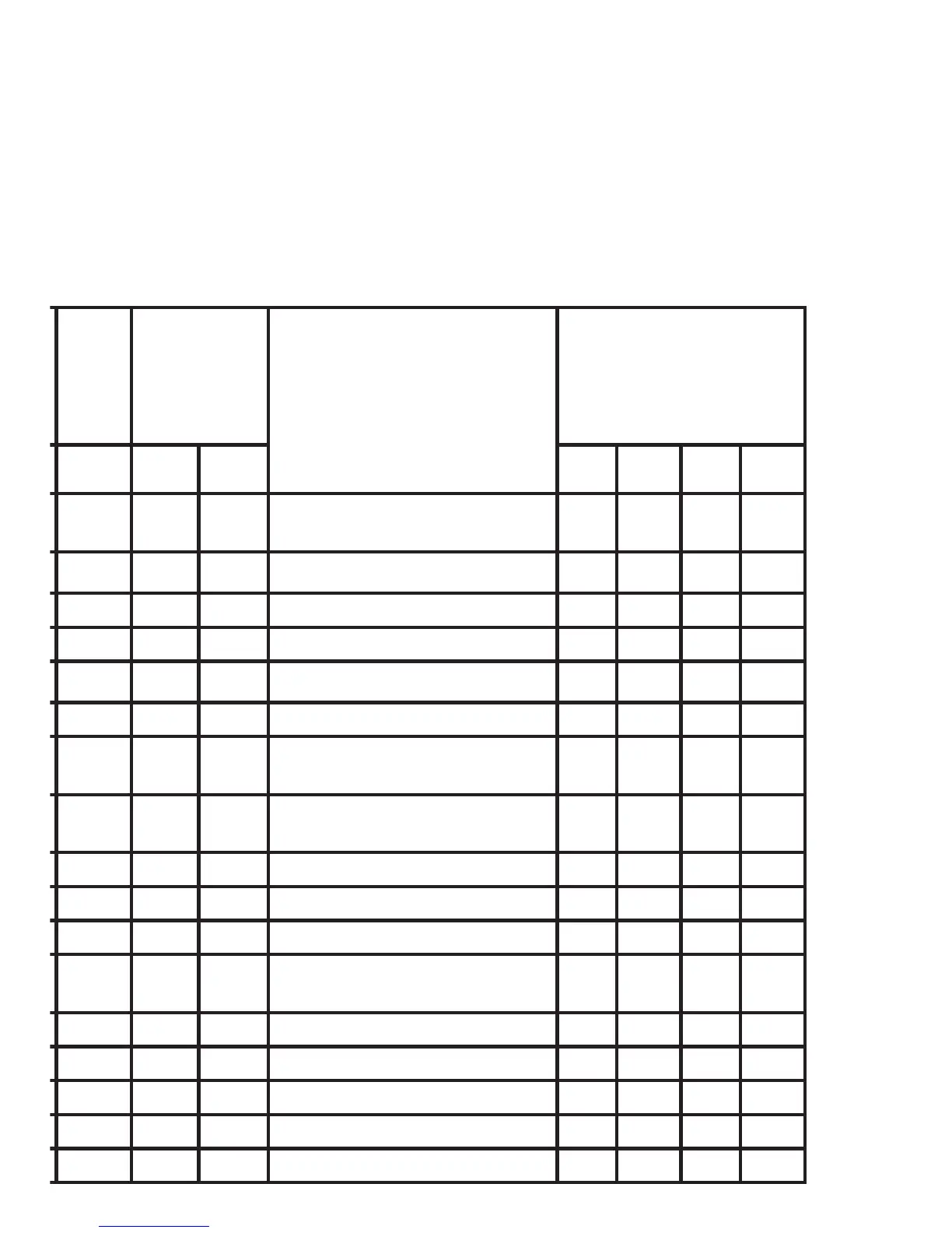
Table B (pages 12-15) should be used. If in any doubt, contact
our Technical Services Department before proceeding with the
replacement. *Any wires connected to switch COMMONS which
are linked LIVE on existing wallplates must be transferred to the
LIVE terminal on the new wallplate
.
HTG
ON
Wires other
than links in
these terms
go to LIVE
NOTE
This conversion applies
only if....
An additional terminal
block may be required
where these discon-
nected leads (or pairs)
should be terminated
4LL
ABCD
625
Programmed
selectors UNLINKED
21-
425
7-- 8
7 5 8 Terminals 5,8 & 10 are LINKED
6 5 7 Terminals 5 & 7 are LINKED
425
Programme
selectors UNLINKED
425
Programme
selectors UNLINKED
385
4--
53- SS
4-5
Programme
selectors UNLINKED
ABCD
4--
2--
165
83-
5--
Wiring Conversions

Other manuals for Danfoss FP715 Si

Questions and Answers:

Question and Answer IconNeed help?

Do you have a question about the Danfoss FP715 Si and is the answer not in the manual?

Danfoss FP715 Si Specifications

General IconGeneral
Battery BackupYes
DisplayLCD
Operating ModeHeating
Number of Channels1
Switching Current3A
Protection ClassIP30
TypeProgrammer
Program7-day, 5/2-day, or 24-hour
Switch Rating3 A (resistive)
Temperature Range5 to 30°C
Power Supply230V AC
Output TypeRelay
Control AlgorithmOn/Off
Operating Temperature0 to 40°C

Related product manuals