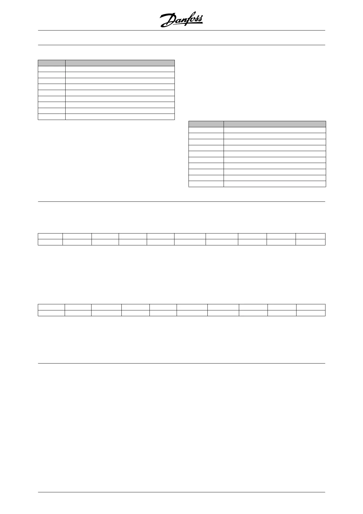
PWE high basic behaviour:
Bit Description
15 Active parameter
14 Array
13 Parameter value can only be reset
12 Parameter value different from factory setting
11 Text available
10 Additional text available
9 Read only
8 Upper and lower limit not relevant
0-7 Data type
Active parameter is only active when communicating
through Profibus.
Array means that the parameter is an array.
If bit 13 is true, the parameter can only be reset, not
written to.
If bit 12 is true, the parameter value is different from
the factory setting.
Bit 11 indicates that text is available.
Bit 10 indicates that additional text is available. Eg.
parameter 001, Language, contains text for index field
0, English, and for index field 1, German.
If bit 9 is true, the parameter value is read-only and
cannot be changed.
If bit 8 is true, upper and lower limits of the parameter
value are not relevant.
PWE
LOW
datatype
Dec. Datatype
3 Signed 16
4 Signed 32
5 Unsigned 8
6 Unsigned 16
7 Unsigned 32
9 Visible string
10 Byte string
13 Time difference
33 Reserved
35 Bit sequence
Example
In this example, the master reads the Basic charac-
teristics of parameter 001, Language. The following
telegram must be sent to the frequency converter:
STX LGE ADR PKE IND PWE
HIGH
PWE
LOW
PCD1 PCD2 BCC
02 0E 01 40 01 00 01 00 00 00 00 XX XX XX XX XX
STX = 02 Start byte
LGE = 0E Length of remaining telegram
ADR = Sends the frequency converter on Address
1, Danfoss format
PKE =
4001; 4 in the PKE field indicates a Read
Parameter Description and 01 indicates pa-
rameter number 001, Language
IND =
0001; 1 indicates that Basic characteristics
are required.
The response from the frequency converter will be:
STX LGE ADR PKE IND PWE
HIGH
PWE
LOW
PCD1 PCD2 BCC
02 0E 01 30 01 00 01 00 00 04 05 XX XX XX XX XX
PKE = 02 Start byte IND = 0001; 1 indicates that
Basic characteristics are sent
PWE
LOW
= 0405; 04 indicates that Basic behaviour as
bit 10 corresponds to Additional text. 05 is the
datatype which corresponds to Unsigned 8.
No of elements (index 2):
This function indicates the Number of elements (array)
of a parameter. The answer to the master will be in
PWE
LOW
.
Conversion and Unit of measurement (index 4):
The Conversion and unit of measurement command
indicates the conversion of a parameter and the unit of
measurement. The answer to the master will be in
PWE
LOW
. The conversion index will be in the high byte
of PWE
LOW
and the unit index will be in the low byte of
PWE
LOW
. Note that conversion index is signed 8 and
unit index is unsigned 8, see tables below.
The unit index defines the “Unit of measure”. The con-
version index defines how the value should be scaled
to get the basic representation of the “Unit of meas-
ure”. Basic representation is where conversion index
equals “0”.
Example:
A parameter has a “unit index” of 9 and a “conversion
index” of 2. The raw (integer) value read is 23. This
means that we have a parameter of the unit “Power”
and the raw value should be multiplied by 10 to the
power of 2 and the unit is W. 23 x 10
2
= 2300 W
Table for conversion and unit of measurement
VLT
®
5000 Design Guide
96 MG.52.B2.02 - VLT
®
is a registered Danfoss trademark

 Loading...


