22
Wiring
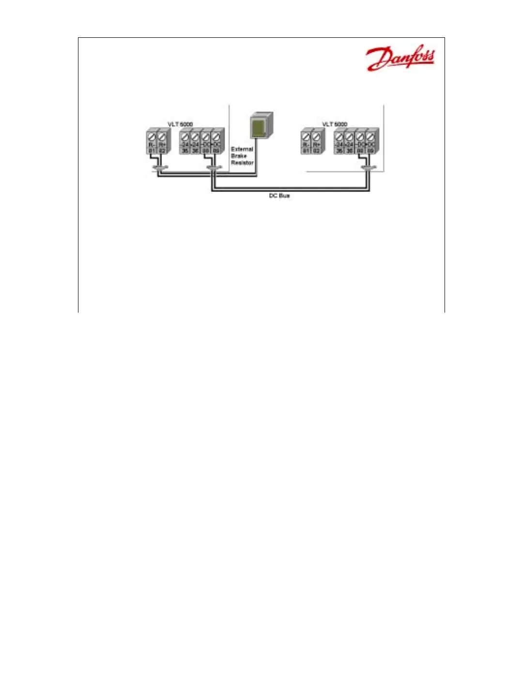
• Brake Wiring on SB & EB units
– Use Terminals 88 & 89 for resistor
– Load sharing for EB units
– External 24Vdc.
On Standard with Brake (SB) units there is an extra terminal labeled R – (81) and R + (82).
The dynamic brake resistor is wired to these 2 terminals. Brake resistors come separately
and are sized using a centrifuge as a model. If over a 2-minute window the dynamic brake is
used infrequently, less than 12 seconds, then a 10% brake resistor is adequate. If over a 2-
minute window the dynamic brake resistor is used a considerable amount of time, 48
seconds, then a 40% brake resistor is used.
On Extended with Brake (EB) units there is an additional terminal block added to the R-, R+
terminals. This terminal block has - DC (88) and + DC (89) which allows one drive to share
its generated power with another drive or drives that requires power.
With the EB unit there is another set of terminals labeled –24 Vdc, Common (35) and +24
Vdc (36) this allows the control card to remain active when main power to the drive is turned
off. This is important for 2 reasons:
1. when using the brake resistor to quickly discharge the DC Link capacitors.
2. When maintaining serial communications.
 Loading...