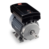
VLT
®
FCM Series
■ Contents
Introduction
......................................................................................................... 3
Safety regulations ..................................................................................................... 4
Warning against unintended start ............................................................................. 4
Introduction .............................................................................................................. 5
Integration of frequency converter and motor ........................................................... 6
Key diagram for FCM 300 Series .............................................................................. 6
Product range .......................................................................................................... 7
Ordering ................................................................................................................... 7
Ordering info for Frames and Flanges ....................................................................... 8
Ordering info for inverter box position and drain hole position ................................... 8
Ordering form ........................................................................................................... 9
Installation ......................................................................................................... 10
FCM 305-375 for 3 phases, 380-480 V .................................................................. 10
General technical data ............................................................................................ 10
Tightening Torques ................................................................................................. 14
Maximum Cable Cross Section .............................................................................. 14
Screw Sizes .......................................................................................................... 14
Description of the motor ......................................................................................... 15
Handling the FC motor .......................................................................................... 16
Bearings ................................................................................................................. 16
Output shafts ......................................................................................................... 16
Dimensions ............................................................................................................ 17
Installation of the FC motor ..................................................................................... 20
Alignment ............................................................................................................... 20
Bolt torques ........................................................................................................... 21
Maintenance ......................................................................................................... 21
Forced ventilation (FV) units (Not yet available) ........................................................ 22
FCM 300 Thermal Protection .................................................................................. 22
Control panel (175NO131) ...................................................................................... 23
LCP installation ..................................................................................................... 23
LCP functions ....................................................................................................... 23
Display ................................................................................................................... 23
LEDs ...................................................................................................................... 24
Control keys ........................................................................................................... 24
Control key functions .............................................................................................. 24
Display read-out state ............................................................................................ 25
Display mode ......................................................................................................... 25
Display mode - selection of read-out state ............................................................. 26
Quick menu mode versus Menu mode ................................................................... 26
Quick Setup via Quick menu .................................................................................. 27
Parameter selection ................................................................................................ 27
Menu mode ............................................................................................................ 27
Parameter groups .................................................................................................. 27
Changing data ........................................................................................................ 28
Changing a text value ............................................................................................. 28
Infinitely variable change of numeric data value ....................................................... 28
Menu structure ....................................................................................................... 29
Service plug kit (175N2546) ................................................................................... 30
Plug kit (175N2545) ................................................................................................ 30
Remote mounting kit (175N0160) ........................................................................... 30
MG.03.H3.02 - VLT is a registered Danfoss trademark
1

 Loading...