01AUG 1005GB Cat.20 / Tab. 05.91 / Page 07.03
Error diagnostics
Error Possible cause Recommended action
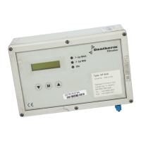
LED 1.1 Fig. 1 is not illuminated
and E1 and E2 are bridged.
• Power failure
• Fuse in controller defect
• The plant’s emergency stop is
activated
• Internal control error
• Check the circuit voltage
• Check the fuses.
• Replace the fuse.
• Check the emergency stop.
• Contact Dantherm Filtration
service
No valve activation
• Defect lead connection
• Defect magnet coil
• Cycle interrupt
• Check cables and cable connec-
tions
• Replace magnet coil.
• Detach pressure difference me-
ter, change the settings and
check the hose connections, etc.
No down-time-cleaning
• DTC cycle = 0
• No signal from fan
(DTC mode 1-2)
• Set other value
• Apply signal to terminals E1
and E2.
The cleaning is inefficient
• Pause period too long
• Cleaning pressure too low
• Valve defect
• Pulse duration too short
• Cleaning cycle often disrupted
• Defect filter system
• Large-scale filters (>160 valves)
where only a part of the filter is
cleaned
• Reduce pause interval 04
• Adjust the pressure to 6-8 bar
(min. 5 bar).
• Pause too short, so pressure is
not reached.
• Check/replace valve.
• Can be modified in setting mode
after consultation with Dan-
therm Filtration.
• Check pressure difference meter
and hose connection.
• Check the filter’s operation in-
structions.
• Set the two main controllers to
the same setting values.
• Check if
∆p -MAX and ∆p -
MIN switching points are set
correctly.
Faulty display of the pressure differ-
ence
• Failure in the hose connections • Empty the hoses.
• Clean the hose connection on
the filter housing with com-
pressed air (blow direction fil-
ter, never in sensor direction).
• Remove any bending on the
hoses.
• Check the hoses inside the con-
trol unit for water, or the like.
NF-8E / NF-16E alarm
• Valve setting wrong
• NF-8E / NF-16E controller de-
fect
• Check the number of valves
• Replace the defect controller


 To Next Page