INSTALLATION
Important safety instructions for the
installation.
Warning: incorrect installation can lead to
severe injury. Follow all the instructions.
To operate a good installation of the gear motor
MAX follow these instructions:
Locate inside the property the correct point to
install MAX, usually near to the support column of
the gate.
Build up a cement emplacement with sizes like fig.
1, foreseeing the passing of the protective
coverings “G” for the passing of the power supply
and control system cables.
Fix, on the surface in cement and perpendicularly
to the gate, the supports “Ps” respecting the
indicated measures (fig. 1).
Put the plate “Pb” on the supports “Ps” and induct
the protective coverings “G” through the holes “F”
(fig. 2).
Fix the plate “Pb” on the supports “Ps” by the
screws “Vp”, and pay attention that the plate “Pb” is
perfectly horizontal (fig. 2).
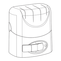
Put the gear motor MAX on the plate “Pb”, take
away the protection cover and fix the Max by
suitable supplied screws “Vf” (fig. 3).
Loose the screws “Vt” and make the plate “Pb” run
in the suitable holes “Fr” to establish a distance
between the operator’s pinion “P” and the gate
suitable to the type of rack “C” you want to install.
The tooth of the pinion must mesh with the teeth of
the rack for all its width (fig. 4).
Carry out an emergency or manual manoeuvre
(see the par. “Emergency or manual manoeuvre”)
and put the gate in the maximum opening position.
Lean one end of the rack “C” on the pinion “P”,
make sure that it’s horizontal and fix it by welding
or by the suitable screws “Vc” (fig. 5), fixing the rack
make slide the gate, checking that the rack don’t
force on the pinion and that don’t go away.
If the gate is crooked put between the gate and the
rack some thickness to assure the constant
centring between the rack and the pinion.
After fixing definitively the rack “C” loose slightly the
screws “Vp” and adjust the play-gap between rack
and pinion (2 mm aprox.) using the plate “Pb” holes
“Fr”, to position correctly the operator (fig. 6).
When everything has been done fix the screws
“Vp” and with a manual manoeuvre open and close
the gate to verify the correct alignment (there have
not been friction).
IMPORTANT
The duration of the rack and the pinion depend on
the right mesh engagement.
The gates must have mechanical stops “Fa” (fig. 7)
in opening and closing to avoid its derailment.
The mechanical stops “Fa” must ensure an antic
rushing space between the mobile and fix part of
the gate,
In conformity with the regulations in force.
Put the gate in opening position and, according to
the gate weight, leave a space of 30-50 mm
between the gate and the mechanical stop “Fa” (fig.
7).
Fix on the rack the limit switch support “S” by grubs
“Gr” in order to push the limit switch (fig. 8).
Repeat the same operation on the other side, for
the closing limit switch support.
Make the circuitry like in the control panel manual
and install the obligatory safety devices.
Teach the people intended for the use of the
automation about the controls, safety devices,
emergency manoeuvre and dangerousness
deriving from the utilize of the automation.
Compile the technical booklet and fulfil the
eventual obligations deriving from the regulations
in force.
We Guarntee the correct functioning of MAX
versions only and exclusively if provided by
DASPI and only if combined with the original
control panel.
EMERGENCY OR MANUAL MANOEUVRE
You have to do the emergency or manual
manoeuvre or during the installation, or only if the
automation does not work properly or if there is not
power supply.
CUT OFF THE POWER SUPPLY.
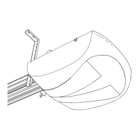
Open the plug on the handle “LS” cover and insert
the supplied key “CH” (fig. 9).
Turn the key “CH” anticlockwise and take out the
handle of 90° towards you (fig. 9) and open the
gate manually.
In order to re-establish the normal functioning of
the automation, you have to put again the handle
“LS” in the original position and turn the key “CH”
clockwise, so take away the key and close the plug
on the handle.
Place the key “CH” in a safety place known
exclusively from the people intended for the use of
the automation.
Switch on the power supply, pay attention that
there’s nobody where the gate is moving.
 Loading...