Do you have a question about the Datakom DKG-507 and is the answer not in the manual?
Unit is a control and protection panel displaying measured values.
Unit is designed for panel mounting on a flat, vertical surface.
WARNING: UNIT IS NOT FUSED. External fuses required for mains, generator, and battery.
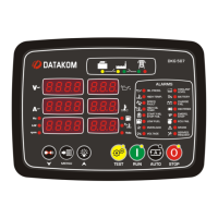
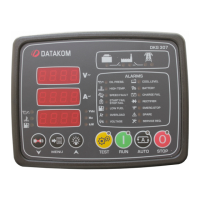
Unit features 12 LEDs in 3 groups: operating mode, mimic diagram, and warnings/alarms.
Unit features 3 seven-segment displays for measured parameters, counters, and program parameters.
Offers REMOTE START mode; SPARE-2 input can be assigned as Remote Start Input.
Unit adapts to various oil pressure and temperature senders with selectable standard characteristics.
Provides two methods for engine heating: timer-controlled or timer/temperature-controlled.
Unit can make/receive modem calls via GSM/PSTN for remote monitoring.
Unit sends SMS for alarms, mains status, fuel theft, or fuelling.
Allows remote monitoring and programming via RS-232 using RAINBOW software.
Offers automatic exerciser operation daily, weekly, or monthly, with or without load.
Procedure to reset unit to factory default settings via button combinations.
Unit firmware can be updated in the field via RS-232 using Rainbow or DOS program.
Details parameters for configuring sender characteristics and input configurations for various switches.
Defines functions of relay outputs, including fixed and programmable relays.
| Maximum Humidity | 95% non-condensing |
|---|---|
| Power Supply | 8 to 35 V-DC |
| Cranking Dropouts | Survive 0 V-DC for 100ms |
| Alternator Frequency | 0 to 100 Hz |
| Magnetic Pickup Voltage | 0.5 to 30 V-AC |
| Magnetic Pickup Frequency | 0 to 10 kHz |
| DC Inputs | 2x Digital Input |
| Operating Temperature | -40 to +70 °C |
| Storage Temperature | -40°C to +80 °C |