Histogram Description
14
DLR-TL001
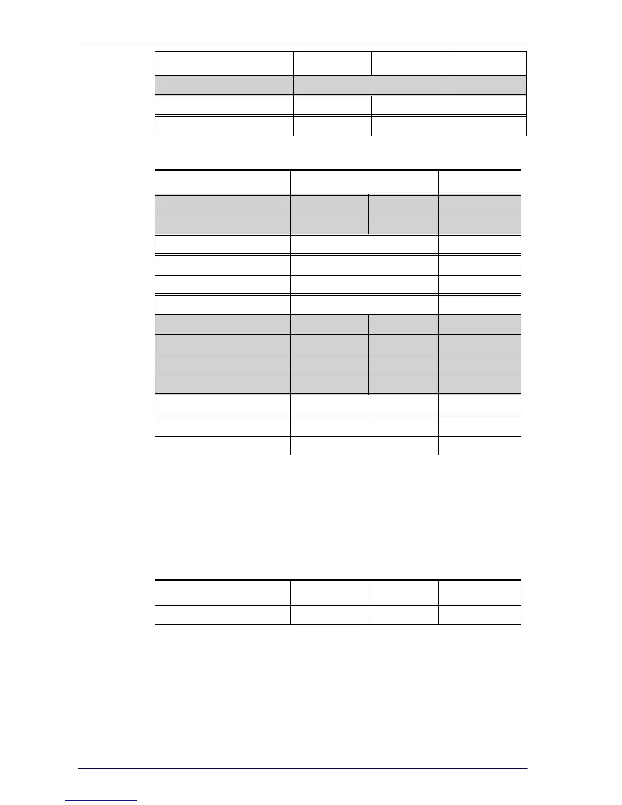
Table 7 - User Memory Map - p. 3
Register Address Op. Default
RFU 0x68 -- --
RFU 0x69 -- --
SHIPPING_DATE_L 0x6A RO 0x0000
SHIPPING_DATE_H 0x6B RO 0x0000
STOP_DATE _L 0x6C RO 0x0000
STOP_DATE _H 0x6D RO
0x0000
USER_AREA_0 0x6E RW --
USER_AREA_1 0x6F RW --
... .. --
USER_AREA_27 0x89 --
LOG_AREA_0 0x8A --
……………………… ………………… --
LOG_AREA_3956 0xFFE --
Register Description
Control Register (RW)
Register Address Op. Default
CONTROL 0x0A RW 0x0010
The CONTROL Register's 16 bits are as follows:
0 - RST
(RW) - Reset bit: is used to erase all the log memory and reset all the
memory pointers and counters included the histogram bins. The value of the
bit remain set until the reset operation is performed then it returns to 0.
Default value is 0.
1 - BE (RW
) - Button_Enable bit: if 1 the DLR-TL001 button can be used to
start and to stop the logging activity. Default is 0.
2 - LE (RW) - Logging_Enable bit: if 1, it enables the logging activity. If the
Button_Enable bit is set the Logging_Enable bit can be set/reset using the
BIN_COUNTER_15 0x65 RO 0x0000
LAST_SAMPLE_VALUE 0x66 RO 0x0000
SAMPLES_NUM 0x67 RO 0x0000
Register Address Op. Default



 To Next Page