1-15
Part No. 001-4008-101/102
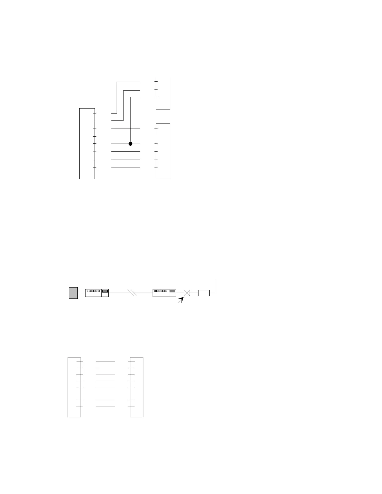
Figure 1-8 Integra-TR Full-duplex Base Station Pinout
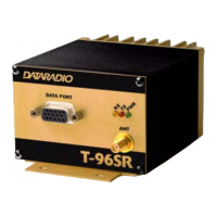
1.10.6 EXTENDING A LANDLINE (TAIL CIRCUIT)
Integra-TR may be used to extend a landline circuit (giving access to difficult locations, etc.). This type of
connection is called a “tail circuit” and is shown in Figure 1-9. The tail circuit assembly may be used in any
of the network types described in the preceding sections.
Figure 1-9 Landline (Tail Circuit)
Note: The line modems should be full duplex units.
Figure 1-10 DCE Crossover Cable for RTS-CTS mode
USER
(DTE)
1
2
3
4
5
6
7
8
RX-Unit (DE-9M)TX-Unit (DE-9M)
DCD
RXD
GND
TXD
GND
DSR
RTS
CTS
DCD
RXD
TXD
DTR
GND
DSR
RTS
CTS
1
2
5
3
5
6
7
8
DE-9F
Y-CABLE
line
modem
line
modem
dedicated
line
Integra
DTE
DCE crossover
cable
1
2
3
4
5
6
7
8
9
DE-9M
7
3
2
8
5
1
4
DE-9M
DCD
RXD
TXD
DTR
GND
RTS
CTS
RTS
TXD
RXD
CTS
GND
DCD
DTR