2-3
Part No. 001-4008-101/102
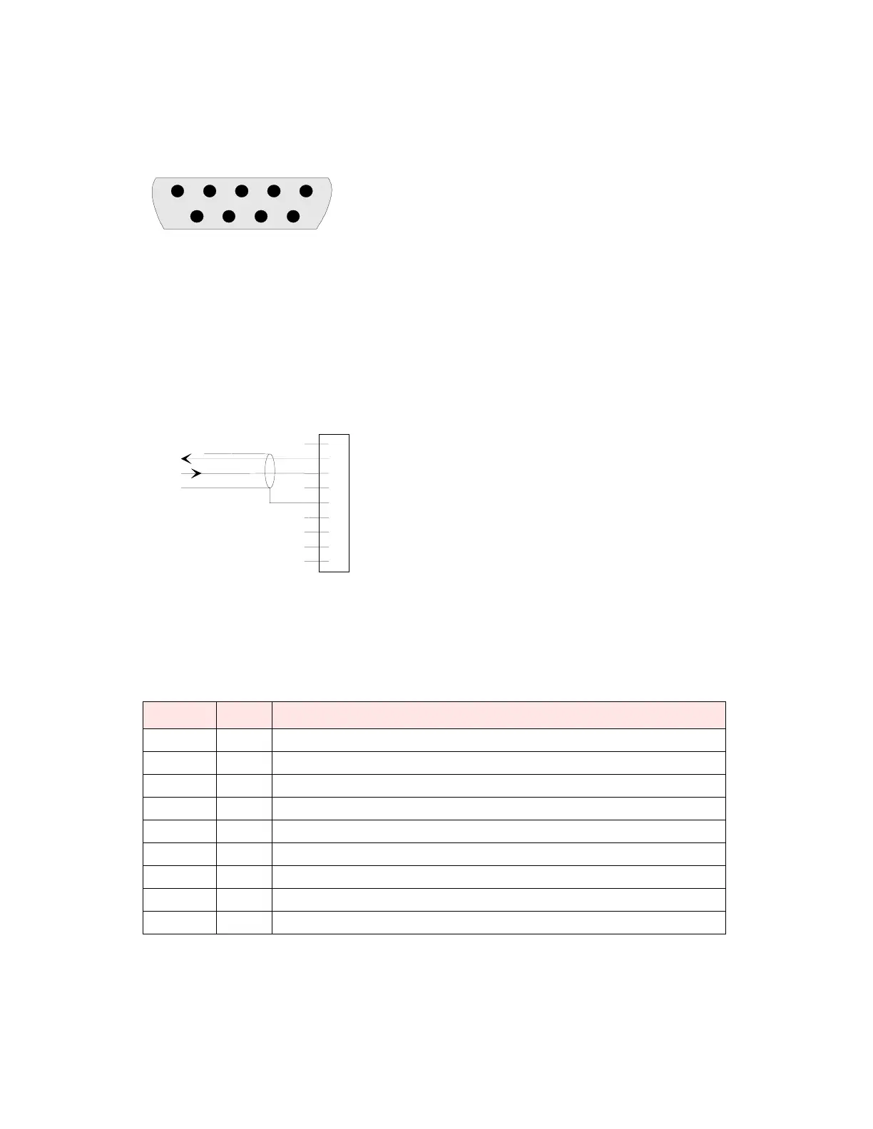
2.2.4.1 Connector Pin Out
The DE-9F pin out is shown in Figure 2.2 for reference.
Figure 2-2 COM and Setup Port Connectors Pin Locations
2.2.4.2 Wire Connection (DOX) Field Programming Software
For DTE that lack RTS control, Integra-TR can operate in DOX mode (Data Operated Transmit) with only
Transmit Data, Receive Data and Ground (“3-wire interface”).
Figure 2-3 3-Wire Interface
2.2.5 Setup Port
The Setup port uses a DE-9 female connector configured as DCE. Signals are described Table 2-4.
Table 2-3 Setup Port Signals
The Setup port uses a proprietary communications protocol designed to work with the Integra-TR Field
Programming Software program. It is also designed to provide numeric diagnostics information when
connected to a PC terminal emulator.
Pin Name Function
1 DCD Tied directly to DTR
2 RXD Data from Integra-TR to setup PC
3 TXD Data from setup PC to Integra-TR
4 DTR Tied directly to DCD
5 GND Signal and chassis ground
6 DSR Output: always positive (asserted)
7 RTS Tied to CTS. Also monitored to “wake up” unit from sleep mode
8CTS Tied to RTS
9 RI Not internally connected, reserved
12345
6789
1
2
3
4
5
6
7
8
9
RXD
TXD
GND
DE-9M