2-4
Part No. 001-4008-101/102
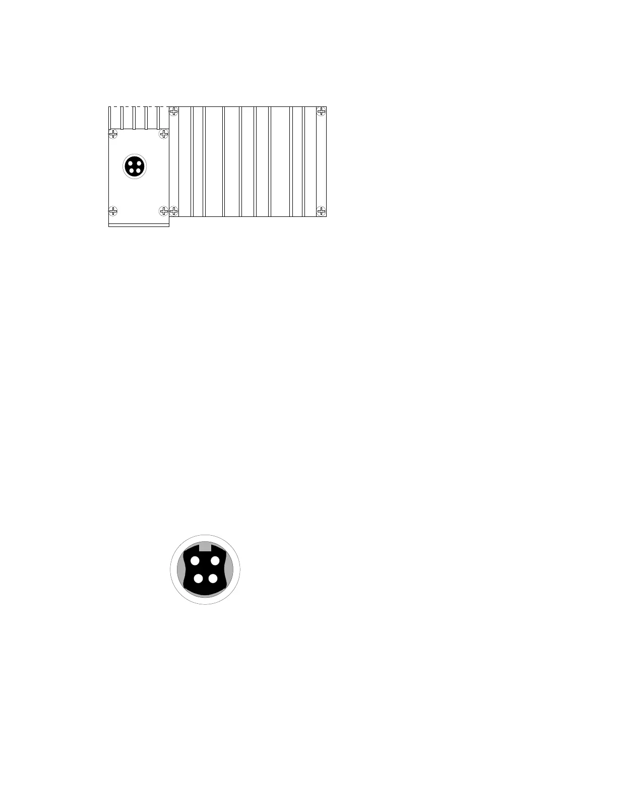
2.3 REAR PANEL
Figure 2-4 Integra-TR rear panel
The various elements are described in the following sections.
2.3.1 Heat Sink
The rear panel heat sink is essential for proper operation of the Integra-TR transmitter. The unit must be
mounted in a location that permits free air circulation past the heat sink. Cooling will be best if the fins are
vertical.
2.3.2 Power
The Integra-TR power requires a regulated power source of 13.3 VDC nominal (10 - 16 VDC max.)
negative ground with a 3.0 A rating. An internal surface-mount 3A fuse (not field-replaceable) and a
crowbar diode protect the main RF power components from reverse polarity. Application of more than 16
VDC will damage the unit and is not covered by the warranty.
WARNING: Do not exceed 16Vdc.
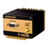
2.3.3 Power / Analog Connector
The 4-pin power / analog connector pin out is shown in Figure 2-5.
Figure 2-5 Analog Connector
Note: The color of the power cable wires are shown in parenthesis. If the analog connections are not used
the green and white wires should be cut back and/or taped to prevent contact. (See Table 1-1 for power
cable part number.)
+13.3 VDC (1)
(2) GND
nalog 1 (3)
(4) Analog 2
RX-TP
(red)
(black)
(white)
(green)