32
RL3
To
DC
Isolator
or AC Assembly
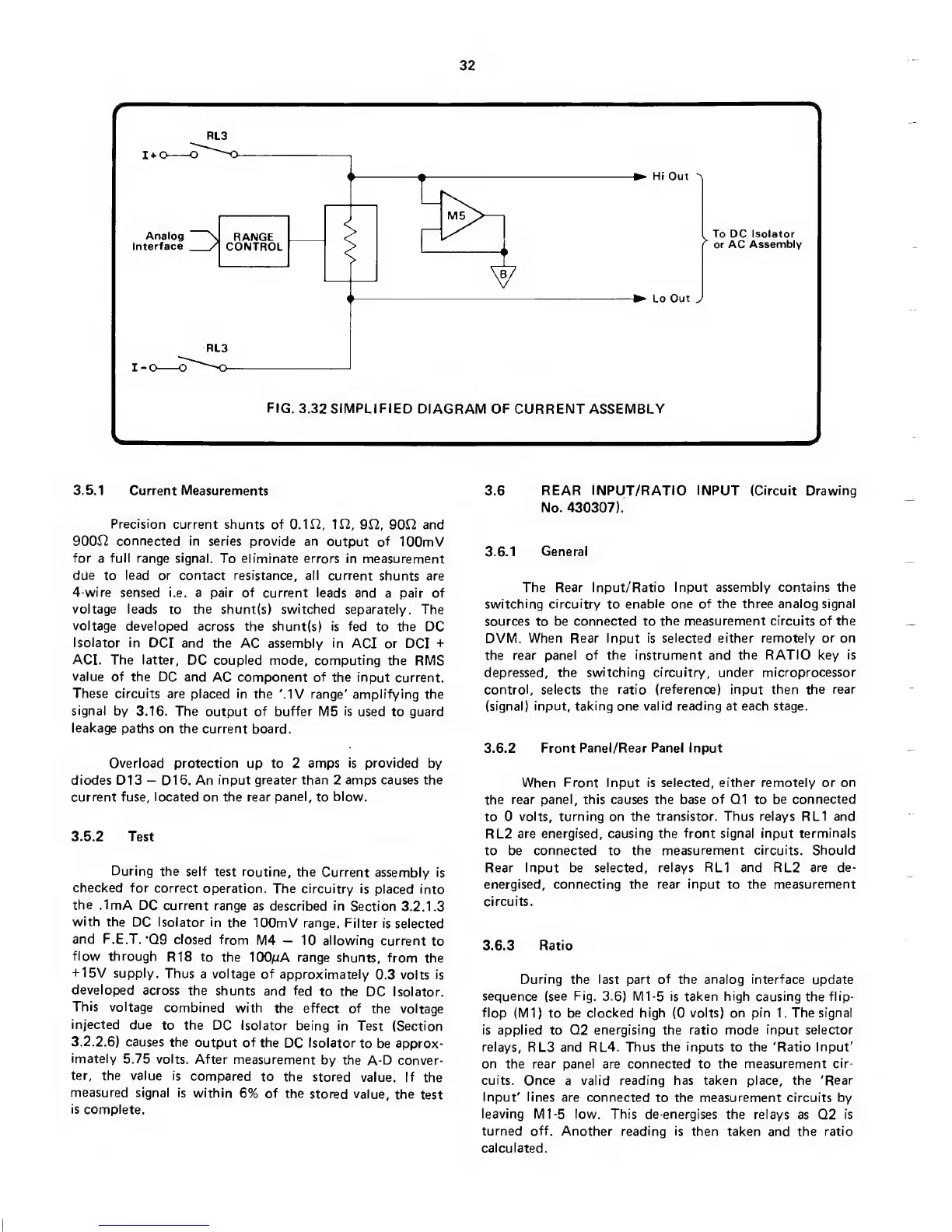
FIG.
3.32 SIMPLIFIED
DIAGRAM
OF
CURRENT ASSEMBLY
3.5.1 Current Measurements
Precision
current shunts of
0.112,
ir2,
9f2,
90r2
and
900J2 connected in series
provide an
output of
lOOmV
for
a
full range signal.
To eliminate errors in
measurement
due
to
lead or contact resistance,
all current
shunts are
4-wire
sensed
i.e.
a pair
of
current leads
and a pair of
voltage
leads
to
the
shunt(s)
switched
separately. The
voltage
developed across the shunt(s) is fed
to the DC
Isolator in
DCI and the AC assembly in
ACI or
DCI
+
ACI. The latter,
DC coupled mode, computing
the RMS
value
of
the
DC and AC component of
the input current.
These circuits
are placed in
the MV range' amplifying
the
signal
by
3.16. The output of buffer
M5
is
used to guard
leakage
paths
on the current
board.
Overload protection up to 2 amps
is provided
by
diodes
D13
—
D16.
An input greater than 2 amps causes the
current fuse,
located
on the rear
panel,
to
blow.
3.5.2 Test
During
the self
test routine,
the
Current assembly
is
checked for
correct
operation. The
circuitry is
placed into
the
.1mA
DC current
range
as described in
Section
3.2. 1.3
with
the
DC Isolator in
the
lOOmV range. Filter
is selected
and
F.E.T.
‘09
closed
from
M4
—
10 allowing
current
to
flow through
R18
to the lOOpA
range
shunts,
from the
H-15V
supply.
Thus
a voltage of
approximately
0.3
volts is
developed
across
the
shunts
and fed
to the
DC Isolator.
This
voltage
combined
with
the effect of
the voltage
injected
due
to the DC Isolator
being in
Test (Section
3.2.2.61
causes
the
output of the
DC Isolator
to be approx-
imately
5.75
volts. After
measurement
by the A-D
conver-
ter,
the value
is
compared
to
the
stored
value. If
the
measured
signal is
within
6% of the
stored
value, the
test
is complete.
3.6
REAR INPUT/RATIO INPUT (Circuit Drawing
No.
430307).
3.6.1
General
The Rear
Input/Ratio Input assembly contains
the
switching circuitry
to
enable one of the three analog signal
sources to be connected to
the measurement circuits of the
DVM.
When Rear Input is selected either remotely
or on
the rear
panel
of the
instrument and the RATIO key is
depressed, the
switching circuitry, under microprocessor
control, selects the
ratio (reference) input then the rear
(signal) input, taking one
valid reading
at each stage.
3.6.2
Front Panel/Rear Panel Input
When Front Input is selected, either remotely or
on
the rear panel, this causes the base
of 01
to
be connected
to 0
volts, turning on the transistor. Thus relays RL1 and
RL2 are energised, causing the
front signal
input
terminals
to be
connected
to
the measurement circuits. Should
Rear Input be selected,
relays
RL1 and RL2 are
de-
energised,
connecting
the
rear input
to the
measurement
circuits.
3.6.3
Ratio
During the last part of
the
analog interface
update
sequence (see Fig.
3.6)
MI-5 is taken high
causing the
flip-
flop
(Ml) to
be clocked high
(0
volts) on pin 1
.
The signal
is
applied
to Q2
energising
the
ratio mode input selector
relays,
RL3
and
RL4.
Thus the
inputs
to the
'Ratio Input'
on
the
rear panel are connected
to
the measurement
cir-
cuits.
Once
a
valid reading has taken place, the
'Rear
Input' lines
are connected
to
the measurement
circuits by
leaving Ml
-5
low. This de-energises
the relays
as Q2
is
turned
off. Another reading is
then taken and the ratio
calculated.
 Loading...