42
M26-1 M
1
1
1 1
UP lUP
M23-21 D
DOWN
DOWN
M23-18 R
4
20mS
^
f
M39-8 F
M23-20 C
FAST
CLOCK
\.SLOW CLOCK
FAST
CLOCK
V-
SLOW CLOCK
¥
r
L
1_
¥
Count
Down Period
•
Count
Up
Period
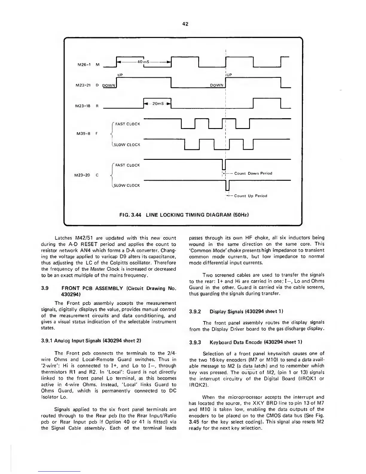
FIG. 3.44 LINE LOCKING
TIMING DIAGRAM
(50Hz)
Latches M42/51 are updated
with
this new count
during
the A-D RESET
period
and
applies
the count to
resistor
network AN4
which forms
a D-A
converter.
Chang-
ing
the
voltage applied
to
varicap
D9
alters its
capacitance,
thus adjusting the
LC
of the Colpitts
oscillator. Therefore
the frequency of the Master Clock is increased
or
decreased
to
be
an exact
multiple of
the
mains frequency.
3.9 FRONT
PCB ASSEMBLY (Circuit Drawing No.
430294)
The Front pcb
assembly accepts the measurement
signals, digitally displays the value,
provides manual
control
of the measurement circuits and
data
conditioning, and
gives
a visual status indication of the selectable instrument
states.
3.9.1
Analog Input Signals (430294 sheet
2)
The Front
pcb connects
the terminals
to
the
2/4-
wire Ohms and Local-Remote Guard switches. Thus
in
'2-wire':
Hi is connected to
I-f,
and Lo to
I—,
through
thermistors
R1
and
R2.
In 'Local': Guard is not directly
linked
to
the
front
panel
Lo
terminal,
as
this becomes
active in 4-wire Ohms. Instead, 'Local' links Guard
to
Ohms
Guard, which is permanently connected
to
DC
Isolator
Lo.
Signals applied
to the
six front panel terminals
are
routed
through to
the
Rear
pcb
(to the
Rear Input/Ratio
pcb or Rear Input pcb
if Option 40 or 41 is fitted)
via
the Signal Cable
assembly.
Each of the terminal leads
passes
through its own
HF choke,
all six inductors
being
wound
in
the
same
direction on the same
core.
This
'Common
Mode' choke
presents
high impedance
to
transient
common mode currents,
but low
impedance
to
normal
mode
differential
input
currents.
Two
screened cables
are used to
transfer the
signals
to the
rear:
I-f
and Hi
are carried
in
one; I—, Lo
and Ohms
Guard
in the other. Guard
is
carried via the cable
screens,
thus guarding
the signals during
transfer.
3.9.2
Display Signals (430294
sheet
1
)
The
front
panel
assembly routes
the
display
signals
from the
Display
Driver
board to
the gas
discharge
display.
3.9.3
Keyboard Data
Encode (430294
sheet
1)
Selection of a
front panel keyswitch
causes
one
of
the two
16-key encoders (M7
or
M10) to
send a
data avail-
able message
to
M2 (a
data
latch) and to
remember
which
key was pressed. The output
of M2,
(pin
1 or
13)
signals
the interrupt circuitry
of
the
Digital Board (IRQK1
or
IRQK2).
When the microprocessor accepts the
interrupt and
has located the source,
the XKY BRD
line
to pin 13
of M7
and M10
is taken low, enabling the data outputs
of the
encoders
to be
placed on
to
the CMOS
data bus (See
Fig.
3.45 for
the
key select coding).
This signal also
resets
M2
ready
for
the
next
key
selection.
 Loading...