Daytronic Corporation
of a
3000
Series instrument, but applicable to any Form 3 instrument. It is the
purpose of this manual to cover the Digital Indicator section of all Form 2 and Form
3 instruments.
The Digital Indicator section of any Form 2 or Form 3 instrument consists of a
printed-circuit board on which are mounted the required circuit components for
digitizing the analog output of the Signal Conditioner and the light-emitting-diode
(LED) display. This board is mounted above the circuit board which contains the
components for the Signal Conditioner. The digits which comprise the display are
mounted on a small board which is affixed to the digitizer board with a right-angle
printed-circuit board header. The Form 3 instruments contain an additional
printed-circuit board for the Hi-Lo Limit circuitry.
The LED display is comprised of six orange digits with polarity sign. The 0.4 inch
height of the digits, combined with the inherent brilliance of an LED type of display,
make the display easily discernible in normal room lighting. The display is viewed
through the red plastic front panel of the instrument to provide filtering of external
light and enhance the display brilliance. The front panel is opaque except for that
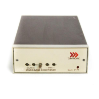
portion through which the display is viewed. A typical 3000 Instrument with Digital
Indicator is shown in Figure 1.
The Digital Indicator scaling is selected with rear-panel pushbutton switches.
Full-scale values of ±5000 counted by
1's,
±
10000 counted by
2's,
or
±20000
counted by
5's
can be selected. The most significant digit (MSD) of the display
contains the polarity sign and is either unlit or lights as a 1 for displays of 10000 or
greater. The least significant digit (LSD) is a dummy zero which can be turned ON
or left unlit as desired. In addition, decimal-point position can be selected to give
display readings as follows:
1.XXXX,
lX.XXX,
1XX.XX,
1XXX.X,
or
1XXXX
(no decimal point). Decimal-point location and dummy zero selection are also
accomplished with rear-panel switches (miniature slide-switch bank). When the
20000 scale is selected, the display is digitally limited to read a maximum number of
19995 since the MSD is either unlit or reads a "1" for displays of 10000 or greater.
The 5000 and 10000 scales are analog limited to an overrange of approximately 5600
and 11200, respectively. An overrange condition on any range is indicated by a
flashing display. The sampling rate of the display is 3 samples per second. The
Digital Indicator specifications are summarized in Table 2.
3
 Loading...