4
3.
AC POWER CONNECTION: Connect the supplied power cable to a 105-135 V-AC,
50-400 Hz source (for "F" versions, 210-260 V-AC; for "B" versions, there
is no external power connection). This is a three-conductor cord, plug-
ing into the AC power connector at the rear of the unit; the offset pin
connects to earth ground. To maintain the safety ground when operating
from a two-contact outlet, use a 3-prong-to-2-prong adapter and connect
the green pigtail on the adapter to earth ground.
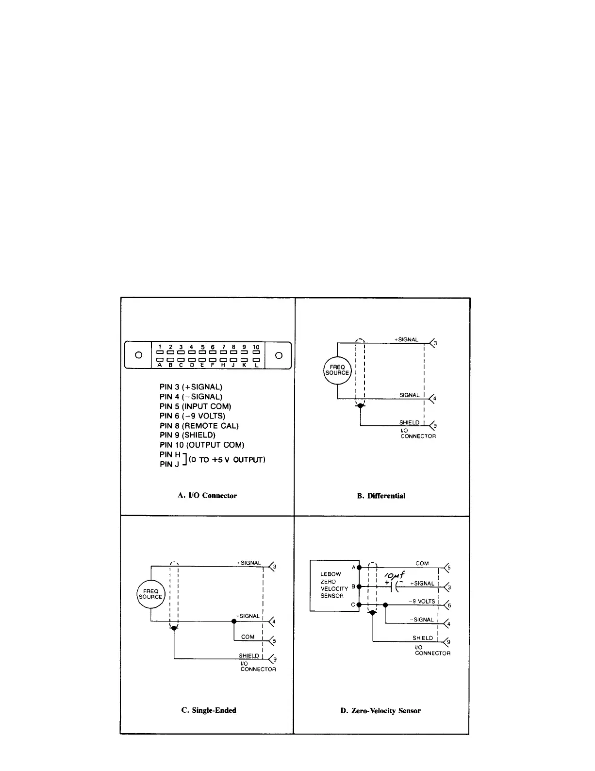
TRANSDUCER CABLING: The transducer is connected via the 3140A's rear-
panel I/O Connector. For pinout, see Fig. 3A, below. The frequency input
can be single-ended or differential, as shown in Fig. 3C and
3B, respecti-
vely. Shielded, twisted-pair cable is recommended. Fig. 3D gives the re-
quired cabling when the 3140A is used with Lebow Zero Velocity Sensors.
Fig. 3 I/O Wiring Data
2.
 Loading...