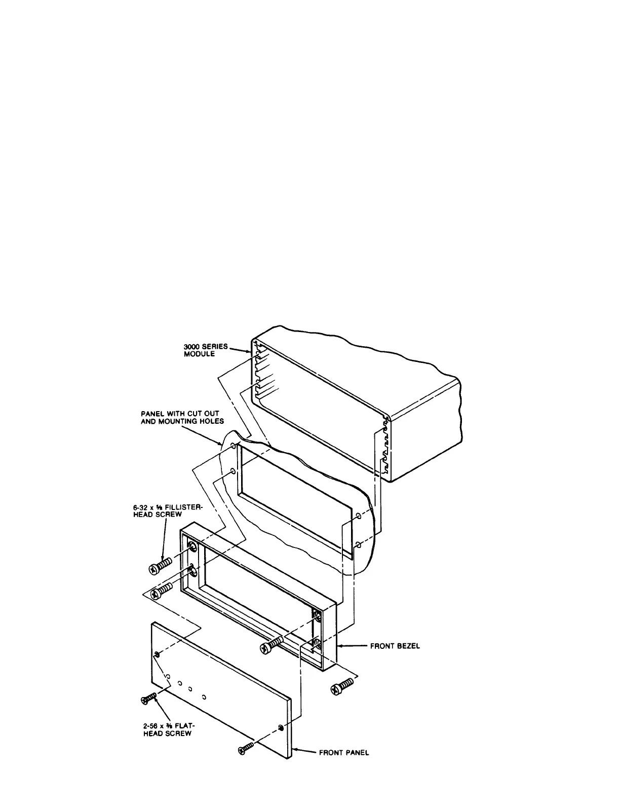
b. Remove the front bezel (four fillister-head screws fasten it to the
metal housing--see Fig. 2).
c. Make the panel cutout and drill the screw clearance holes shown in
Figs. 1C and 2. The front bezel can be used as a template to define
the rectangular cutout and to locate the clearance holes.
d. Hold the instrument behind the panel and use the four mounting screws
to reattach the front bezel to the metal housing, from the front of the
panel.
e.
Reinstall the front panel.
f. Tighten--BUT DON'T OVERTIGHTEN--the two securing screws of the rear-
panel I/O Connector. This will push forward the printed-circuit board
and all front-panel buttons and controls by about 1/8"--which is conse-
quently the maximum panel thickness allowed.
Fig. 2 Instrument
Panel Mounting
3
 Loading...