4.
5.
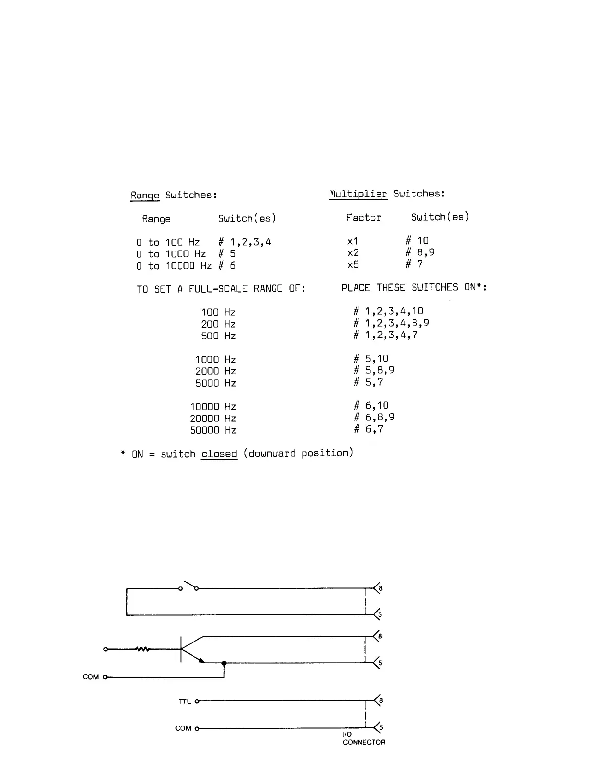
RANGE SELECTION: To access the internal bank of ten numbered range-
selection switches, remove the 3140A's front panel (two screws near each
edge--see Fig. 2). To select the desired full-scale frequency range,
place in the ON (i.e., downward) position the switches indicated in Table
2, below.
Table 2. Frequency Range Selection
REMOTE CALIBRATION CHECK: The 3140A can be placed in the REMOTE CAL mode
by connecting Pin 5 of the I/O Connector (Signal Common) to Pin 8. This
provides a means of periodically monitoring the instrument from a remote
location without pressing the front-panel CAL button. When the Remote Cal
input (Pin 8) is brought to a 0-volt (ground) level through the action of
an external switch, transistor driver, etc. (see Fig.
4), the effect is the
same as when the CAL button is pushed (see Section III, below).
Fig. 4 Remote Calibration
Connections
5
 Loading...