13
INSTALLATION
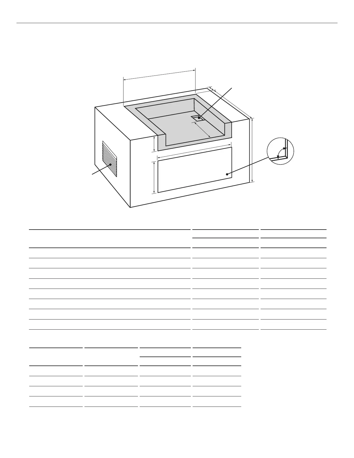
CAVITY DIMENSIONS
BH1-48R BH1-36R
Inches (mm) Inches (mm)
A
Maximum height of enclosure shell
35
½ (902) 35 ½ (902)
B
Depth of enclosure shell
23
¾ (603)
23 ¾ (603)
C
Minimum depth for hood swing
18
¾ (476)
18 ¾ (476)
D
Width of enclosure cavity
51
⅝ (1318) 40 ½ (1029)
E
Height of enclosure cavity
11
⅛ (283) 11 ⅛ (283)
f
Depth to gas supply opening
18
½ (470) 18 ½ (470)
G
Height of opening for access doors/drawers
20 (508) 20 (508)
H
Width of opening for access doors/drawers
46 (1168) 34 (864)
ACCESS DOORS
MODEL NUMBER
ACCESS DRAWERS
MODEL NUMBER
CAVITY WIDTH CAVITY HEIGHT
Inches (mm) Inches (mm)
ADN1-20x48 ADR2-48 46 (1168) 20 (508)
ADN1-20x36 ADR2-36 34 (864) 20 (508)
ADN1-20x30 ADR2-30 28 (711) 20 (508)
ADN1-20x24 ADR2-24 22 (559) 20 (508)
D
E
G
H
B
C
F
Built-in Construction Details
Standard layout for cavity including insulated jacket
Note: the enclosure should have
ventilation holes to prevent gas
build-up in the event of a leak.
Refer to ANSI Z21.58 Standard for
Outdoor Cooking Gas Appliances,
Section 1.7 Enclosures For Self
Contained LP-Gas Supply Systems.
Note: the cut-out of
each corner should be a
90°angle in order for the
access doors/drawers to
fit properly.
Note: 4x4” (102mm x 102mm)
opening for gas supply line.
FIG. 05
To order access drawers or doors, please visit www.dcsappliances.com for further details.
EN